
How to Use JC3248W535C Esp32: Examples, Pinouts, and Specs
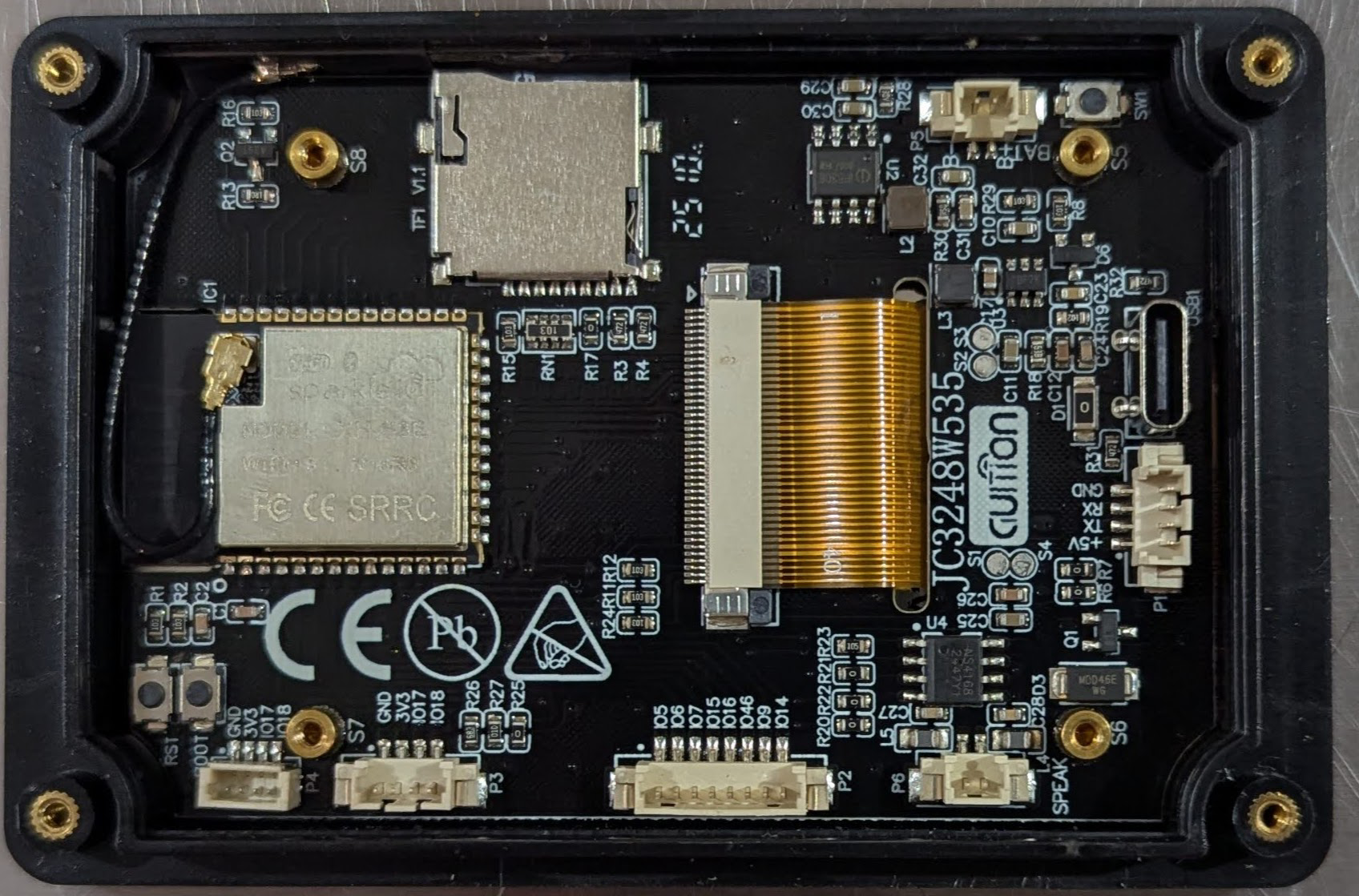
 Design with JC3248W535C Esp32 in Cirkit Designer
Introduction
The JC3248W535C Esp32, manufactured by GUItion, is a high-performance, low-power microcontroller module designed for IoT (Internet of Things) applications. It features dual-core processing, integrated Wi-Fi, and Bluetooth capabilities, making it ideal for wireless communication and smart device integration. This module is widely used in home automation, wearable electronics, industrial IoT systems, and robotics.
The JC3248W535C Esp32 is particularly valued for its versatility, compact size, and robust connectivity options. It supports a wide range of peripherals and protocols, making it suitable for both hobbyist projects and professional applications.
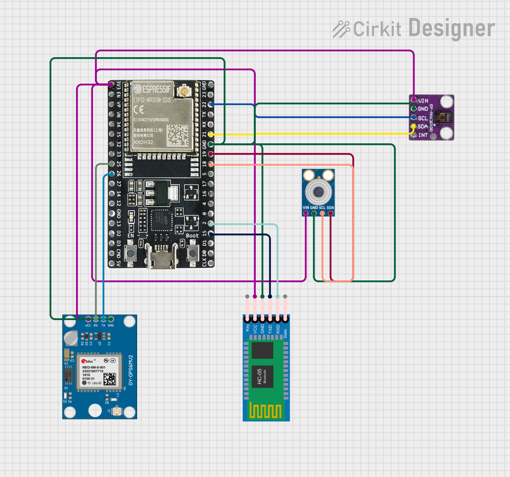
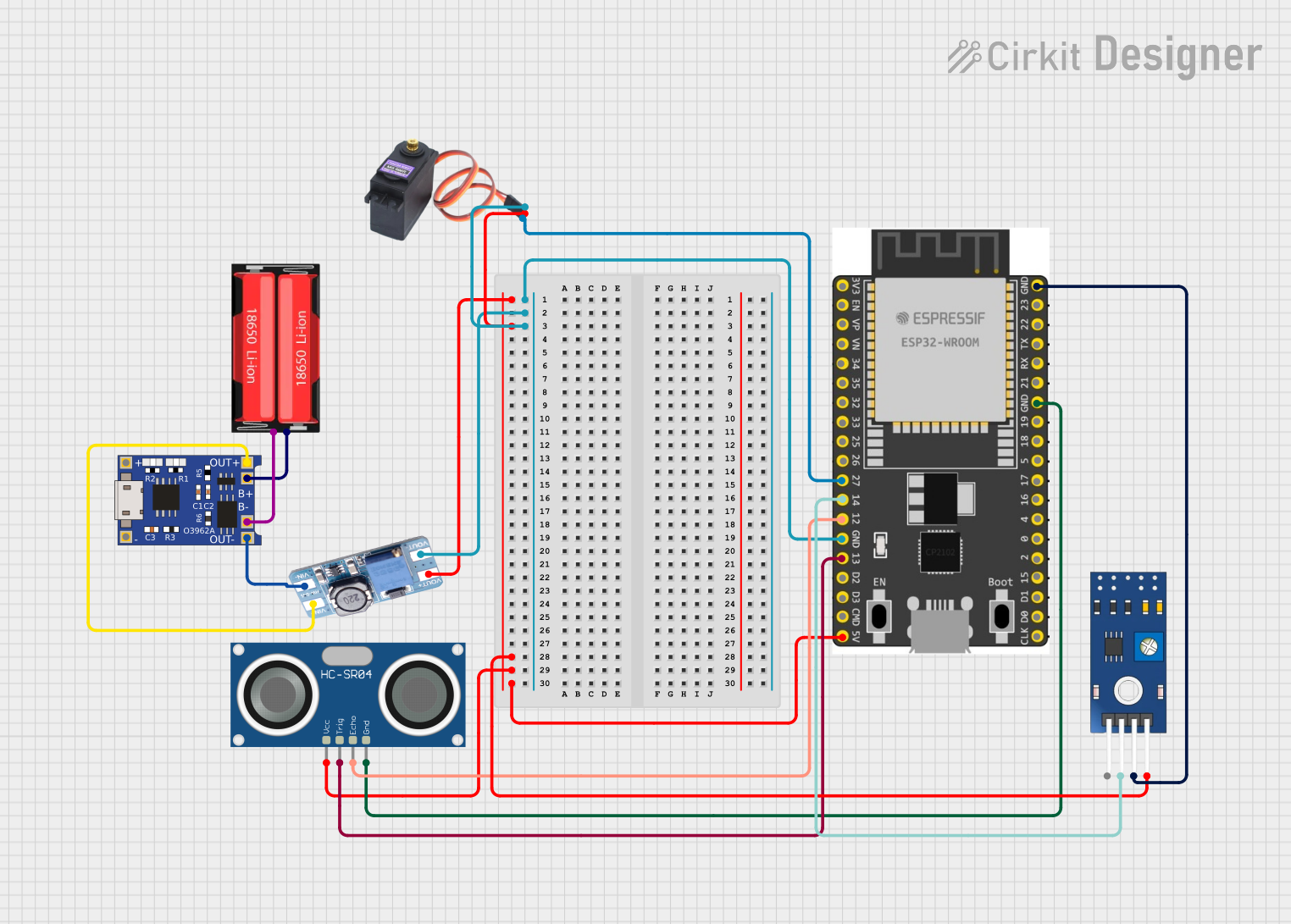
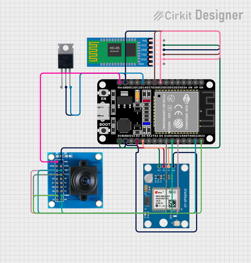
Explore Projects Built with JC3248W535C Esp32
 Open Project in Cirkit Designer
 Open Project in Cirkit Designer
 Open Project in Cirkit Designer
 Open Project in Cirkit Designer
Explore Projects Built with JC3248W535C Esp32
Open Project in Cirkit DesignerOpen Project in Cirkit DesignerOpen Project in Cirkit DesignerOpen Project in Cirkit DesignerTechnical Specifications
Below are the key technical details of the JC3248W535C Esp32:
General Specifications
| Parameter | Value |
|---|---|
| Manufacturer | GUItion |
| Part ID | JC3248W535 |
| Microcontroller | Xtensa® dual-core 32-bit LX6 |
| Operating Voltage | 3.3V |
| Flash Memory | 4MB |
| SRAM | 520KB |
| Wi-Fi Standard | 802.11 b/g/n |
| Bluetooth Version | v4.2 BR/EDR and BLE |
| Operating Temperature | -40°C to +85°C |
| Dimensions | 25.5mm x 18mm x 3mm |
Electrical Characteristics
| Parameter | Min Value | Typical Value | Max Value |
|---|---|---|---|
| Input Voltage (VDD) | 2.7V | 3.3V | 3.6V |
| Digital I/O Voltage | 0V | 3.3V | 3.6V |
| Current Consumption | 10µA | 80mA | 240mA |
| Wi-Fi Transmit Power | - | 19.5dBm | - |
Pin Configuration
The JC3248W535C Esp32 module has 38 pins. Below is a summary of the key pins:
| Pin Number | Pin Name | Description |
|---|---|---|
| 1 | EN | Enable pin (active high) |
| 2 | IO0 | GPIO0, used for boot mode selection |
| 3 | IO1 | GPIO1, UART TX |
| 4 | IO3 | GPIO3, UART RX |
| 5 | IO4 | GPIO4, PWM capable |
| 6 | IO5 | GPIO5, PWM capable |
| 7 | GND | Ground |
| 8 | 3V3 | 3.3V power supply |
| 9 | IO12 | GPIO12, ADC capable |
| 10 | IO13 | GPIO13, ADC capable |
| ... | ... | ... (refer to the full datasheet) |
Usage Instructions
How to Use the JC3248W535C Esp32 in a Circuit
- Power Supply: Connect the 3.3V pin to a stable 3.3V power source and GND to ground.
- Programming: Use a USB-to-serial adapter to connect the UART TX and RX pins to your computer for programming. Ensure the EN pin is pulled high.
- Boot Mode: To enter bootloader mode, hold GPIO0 low while resetting the module.
- Peripherals: Connect sensors, actuators, or other peripherals to the GPIO pins. Use ADC pins for analog inputs and PWM-capable pins for motor control or LED dimming.
Important Considerations
- Voltage Levels: Ensure all connected devices operate at 3.3V logic levels to avoid damaging the module.
- Heat Management: If operating at high power for extended periods, consider adding a heatsink or ensuring proper ventilation.
- Antenna Placement: For optimal Wi-Fi and Bluetooth performance, avoid placing the module near metal objects or inside enclosures that block RF signals.
Example Code for Arduino UNO
The JC3248W535C Esp32 can be programmed using the Arduino IDE. Below is an example of how to connect the module to a Wi-Fi network:
#include <WiFi.h> // Include the Wi-Fi library for ESP32

const char* ssid = "Your_SSID";       // Replace with your Wi-Fi network name
const char* password = "Your_Password"; // Replace with your Wi-Fi password

void setup() {
  Serial.begin(115200); // Initialize serial communication at 115200 baud
  delay(1000);          // Wait for a moment to stabilize

  Serial.println("Connecting to Wi-Fi...");
  WiFi.begin(ssid, password); // Start connecting to the Wi-Fi network

  while (WiFi.status() != WL_CONNECTED) {
    delay(500); // Wait for connection
    Serial.print(".");
  }

  Serial.println("\nConnected to Wi-Fi!");
  Serial.print("IP Address: ");
  Serial.println(WiFi.localIP()); // Print the assigned IP address
}

void loop() {
  // Add your main code here
}
Notes:
- Install the ESP32 board package in the Arduino IDE before uploading the code.
- Ensure the correct COM port and board type are selected in the IDE.
Troubleshooting and FAQs
Common Issues
Module Not Powering On:
- Ensure the power supply provides a stable 3.3V.
- Check for loose connections or damaged wires.
Wi-Fi Connection Fails:
- Verify the SSID and password are correct.
- Ensure the router is within range and not blocking the device.
Code Upload Fails:
- Check that the correct COM port and board type are selected in the Arduino IDE.
- Ensure GPIO0 is held low during the reset for bootloader mode.
Overheating:
- Reduce the module's workload or improve ventilation.
FAQs
Q: Can the JC3248W535C Esp32 operate at 5V?
A: No, the module operates at 3.3V. Exposing it to 5V may damage the device.
Q: How many GPIO pins are available?
A: The module has 34 GPIO pins, many of which support ADC, PWM, and other functions.
Q: Can I use the JC3248W535C Esp32 for Bluetooth audio?
A: Yes, the module supports Bluetooth Classic and BLE, which can be used for audio streaming with appropriate libraries.
Q: Is the module compatible with Arduino libraries?
A: Yes, the JC3248W535C Esp32 is compatible with most Arduino libraries, especially those designed for ESP32.
This concludes the documentation for the JC3248W535C Esp32. For further details, refer to the official datasheet or GUItion's support resources.