
How to Use Rasberry Pi5: Examples, Pinouts, and Specs
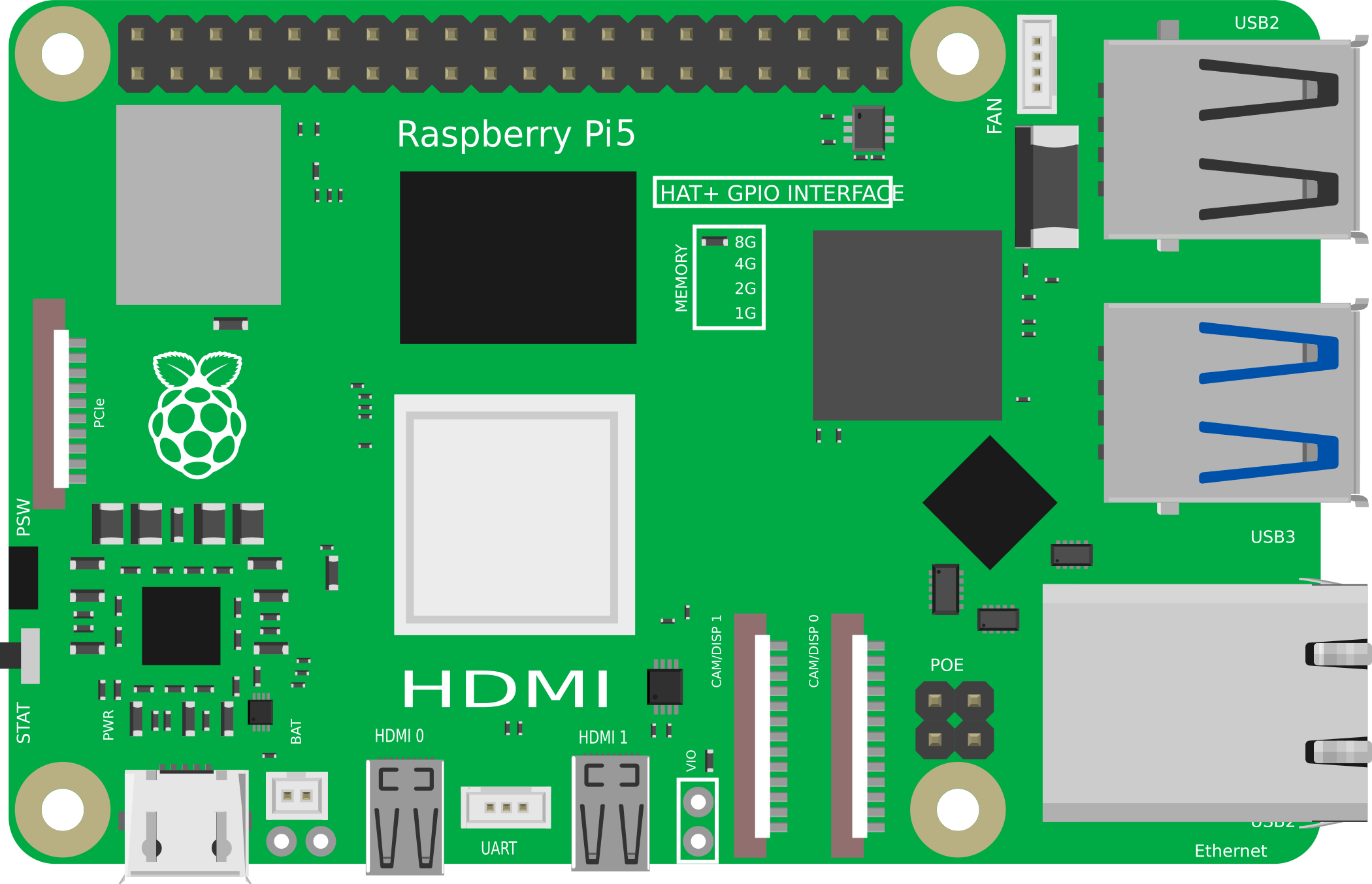
 Design with Rasberry Pi5 in Cirkit Designer
Introduction
The Raspberry Pi 5 is a compact, affordable single-board computer designed for a wide range of applications. It supports various programming languages, making it an ideal choice for beginners and professionals alike. With its powerful processing capabilities and versatile GPIO pins, the Raspberry Pi 5 is perfect for projects in electronics, robotics, IoT, and more. Its small form factor and affordability make it accessible for hobbyists, educators, and developers.
Explore Projects Built with Rasberry Pi5
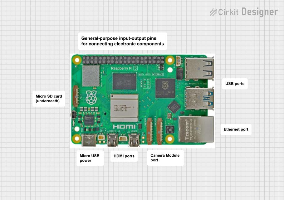 Open Project in Cirkit Designer
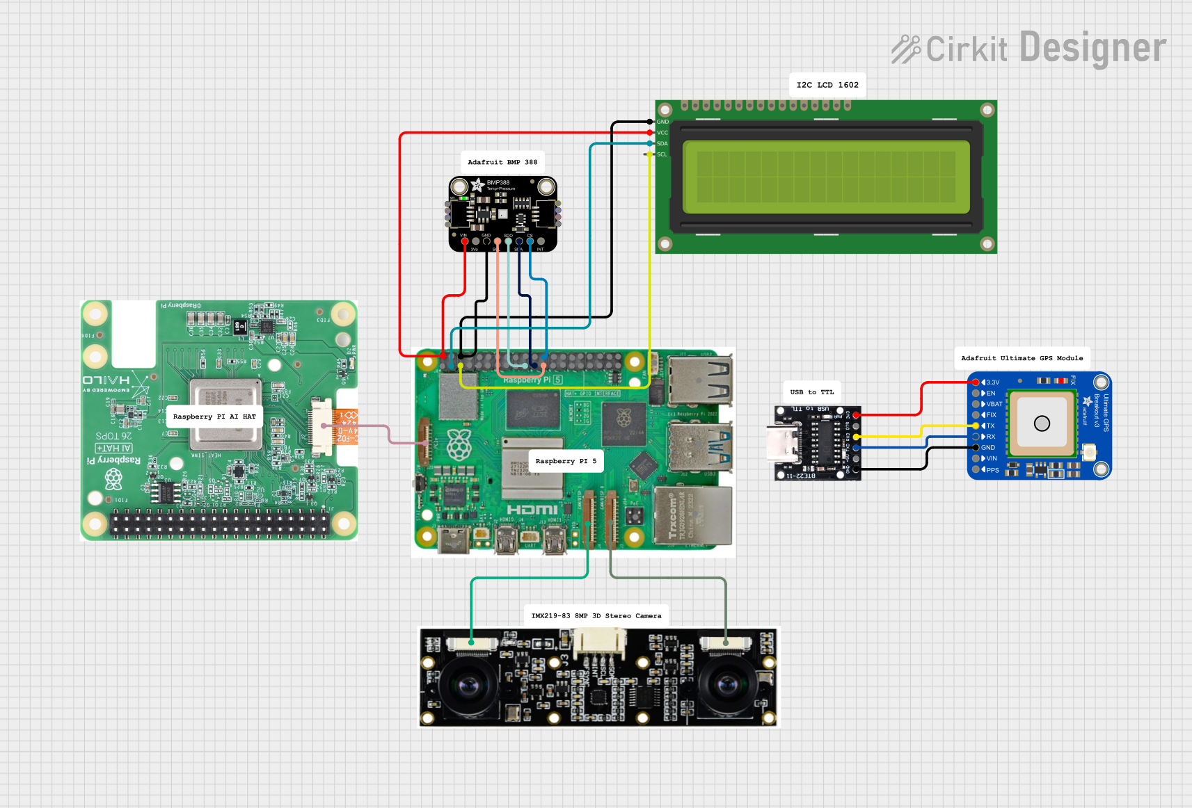 Open Project in Cirkit Designer
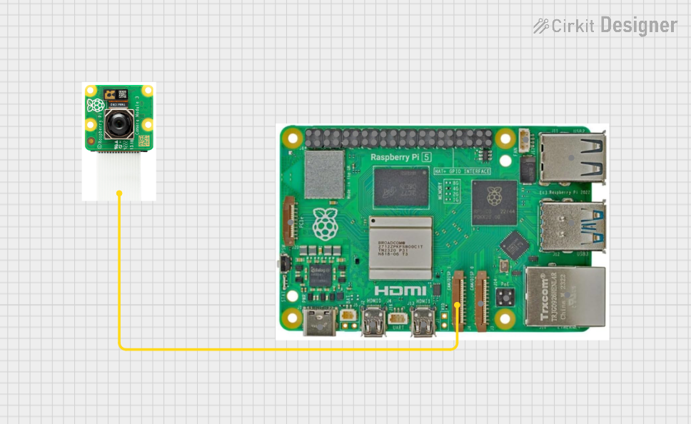 Open Project in Cirkit Designer
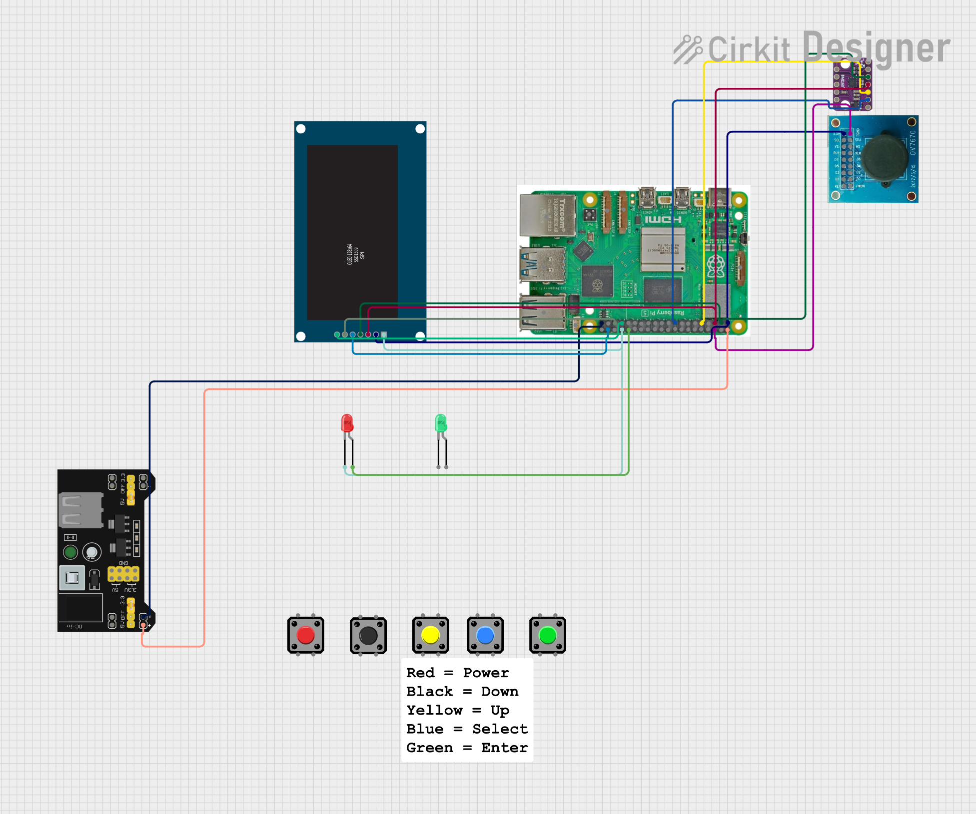 Open Project in Cirkit Designer
Explore Projects Built with Rasberry Pi5
Open Project in Cirkit DesignerOpen Project in Cirkit DesignerOpen Project in Cirkit DesignerOpen Project in Cirkit DesignerCommon Applications and Use Cases
- Home automation and IoT projects
- Robotics and motor control systems
- Media centers and streaming devices
- Educational tools for learning programming and electronics
- Prototyping and product development
- Network servers and lightweight computing tasks
Technical Specifications
The Raspberry Pi 5 offers significant improvements over its predecessors, with enhanced performance and connectivity options. Below are the key technical details:
General Specifications
| Feature | Specification |
|---|---|
| Processor | Quad-core ARM Cortex-A76 @ 2.4 GHz |
| GPU | VideoCore VII |
| RAM | 4GB or 8GB LPDDR4X |
| Storage | MicroSD card slot, eMMC module support |
| Connectivity | Gigabit Ethernet, Wi-Fi 6, Bluetooth 5.2 |
| USB Ports | 2x USB 3.0, 2x USB 2.0 |
| GPIO Pins | 40-pin header |
| Display Output | 2x micro-HDMI (4K@60Hz) |
| Power Supply | USB-C (5V/5A recommended) |
| Dimensions | 85.6mm x 56.5mm x 17mm |
GPIO Pin Configuration
The Raspberry Pi 5 features a 40-pin GPIO header for interfacing with external components. Below is the pinout:
| Pin Number | Function | Description |
|---|---|---|
| 1 | 3.3V Power | Power supply (3.3V) |
| 2 | 5V Power | Power supply (5V) |
| 3 | GPIO2 (SDA1) | I2C Data Line |
| 4 | 5V Power | Power supply (5V) |
| 5 | GPIO3 (SCL1) | I2C Clock Line |
| 6 | Ground | Ground |
| 7 | GPIO4 | General Purpose I/O |
| 8 | GPIO14 (TXD) | UART Transmit |
| 9 | Ground | Ground |
| 10 | GPIO15 (RXD) | UART Receive |
| ... | ... | ... |
| 39 | Ground | Ground |
| 40 | GPIO21 | General Purpose I/O |
For the full GPIO pinout, refer to the official Raspberry Pi documentation.
Usage Instructions
How to Use the Raspberry Pi 5 in a Circuit
- Powering the Raspberry Pi 5: Use a USB-C power adapter capable of delivering 5V/5A to ensure stable operation.
- Connecting Peripherals: Attach a keyboard, mouse, and monitor via USB and HDMI ports. Alternatively, use SSH or VNC for headless operation.
- Booting the OS: Flash a compatible operating system (e.g., Raspberry Pi OS) onto a microSD card or eMMC module. Insert the storage device into the appropriate slot and power on the board.
- Using GPIO Pins: Connect external components (e.g., LEDs, sensors) to the GPIO pins. Use Python or other supported programming languages to control the pins.
Important Considerations and Best Practices
- Always power off the Raspberry Pi before connecting or disconnecting components to avoid damage.
- Use resistors when connecting LEDs or other components to GPIO pins to prevent overcurrent.
- Ensure proper cooling (e.g., heatsinks, fans) for intensive tasks to avoid thermal throttling.
- Regularly update the operating system and firmware for optimal performance and security.
Example: Blinking an LED with Python
Below is an example of how to blink an LED connected to GPIO pin 17 using Python:
Import the GPIO library and time module
import RPi.GPIO as GPIO import time
Set up GPIO mode and pin
GPIO.setmode(GPIO.BCM) # Use Broadcom pin numbering GPIO.setup(17, GPIO.OUT) # Set GPIO 17 as an output pin
try: while True: GPIO.output(17, GPIO.HIGH) # Turn on the LED time.sleep(1) # Wait for 1 second GPIO.output(17, GPIO.LOW) # Turn off the LED time.sleep(1) # Wait for 1 second except KeyboardInterrupt: # Clean up GPIO settings on exit GPIO.cleanup()
Running the Code
- Connect an LED to GPIO pin 17 with a 330-ohm resistor in series.
- Save the code as
blink.pyon your Raspberry Pi. - Run the script using the command:
python3 blink.py.
Troubleshooting and FAQs
Common Issues
The Raspberry Pi does not boot:
- Ensure the power supply meets the 5V/5A requirement.
- Check that the microSD card or eMMC module is properly inserted and contains a valid OS image.
No display on the monitor:
- Verify the HDMI cable is securely connected.
- Ensure the monitor is set to the correct input source.
- Check for compatibility with the micro-HDMI port.
GPIO pins not working:
- Confirm the correct pin numbering (BCM vs. physical).
- Check for loose connections or damaged components.
- Ensure the GPIO library is installed and configured correctly.
Tips for Troubleshooting
- Use a multimeter to check voltage levels on GPIO pins.
- Refer to the Raspberry Pi forums and community for additional support.
- Update the firmware using the command:
sudo rpi-update.
By following this documentation, you can effectively utilize the Raspberry Pi 5 for a variety of projects and applications.