How to Use MMWave radar sensor: Examples, Pinouts, and Specs
Introduction
The MMWave (Millimeter Wave) radar sensor is an advanced electronic component that operates in the millimeter-wave frequency spectrum. It is designed for precise object detection, distance measurement, and speed tracking. MMWave radar sensors are widely used in various applications, including automotive safety systems, such as adaptive cruise control and collision avoidance, as well as in industrial automation, smart home applications, and robotics.
Explore Projects Built with MMWave radar sensor
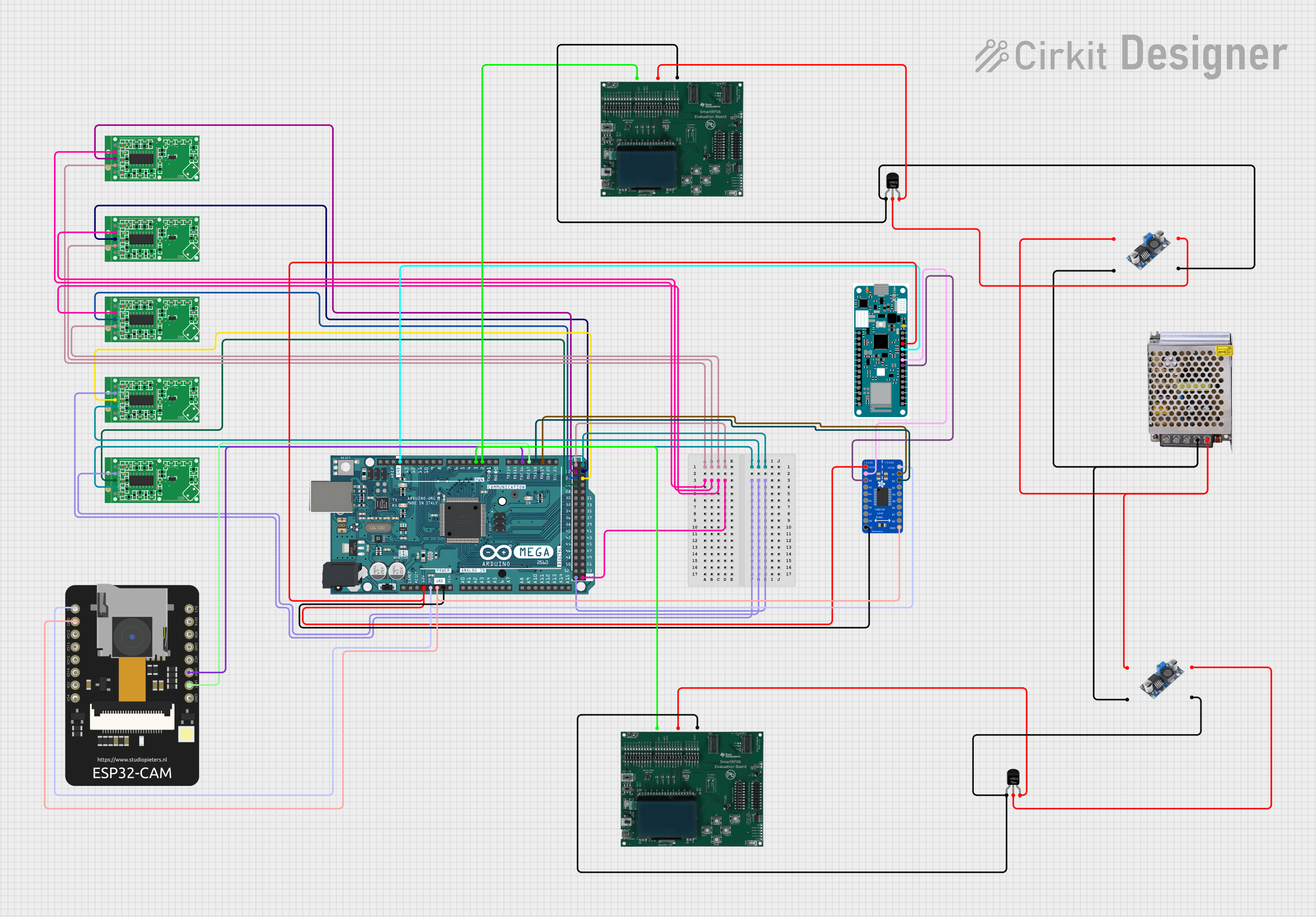
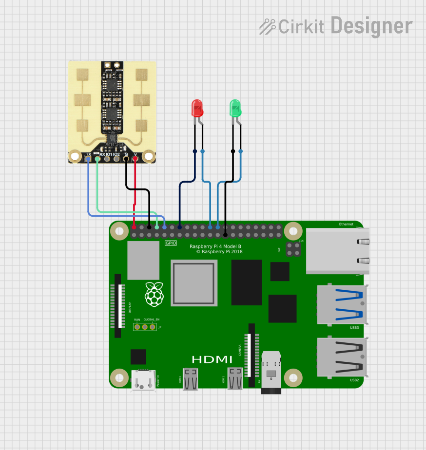

Explore Projects Built with MMWave radar sensor
Technical Specifications
Key Technical Details
- Frequency Range: Typically 24 GHz to 81 GHz
- Detection Range: Varies by model (e.g., 0.1 to 100 meters)
- Field of View: Dependent on antenna design (e.g., 15° to 160°)
- Resolution: Ability to distinguish between objects, specified in degrees or meters
- Output Power: Regulated by local laws (e.g., <20 dBm)
- Interface: Common interfaces include SPI, I2C, UART, or CAN
- Operating Temperature: Range in which the sensor can operate reliably (e.g., -40°C to +85°C)
- Supply Voltage: Typical range (e.g., 3.3V to 5V)
- Current Consumption: Typical and maximum values (e.g., 100 mA typical, 200 mA max)
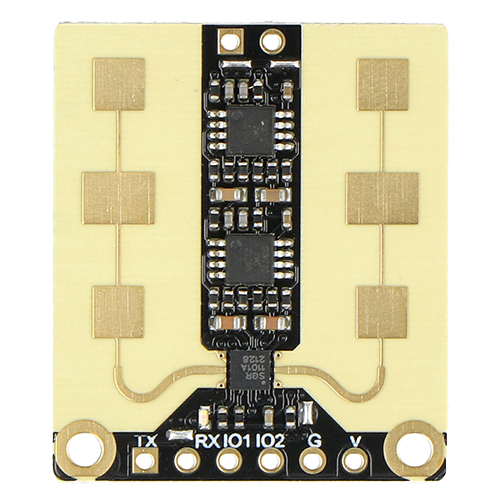
Pin Configuration and Descriptions
| Pin Number | Name | Description |
|---|---|---|
| 1 | VDD | Power supply voltage input |
| 2 | GND | Ground connection |
| 3 | SCLK | Serial Clock for SPI communication |
| 4 | MISO | Master In Slave Out for SPI communication |
| 5 | MOSI | Master Out Slave In for SPI communication |
| 6 | CS | Chip Select for SPI communication |
| 7 | SDA | Serial Data for I2C communication |
| 8 | SCL | Serial Clock for I2C communication |
| 9 | TX | Transmit pin for UART communication |
| 10 | RX | Receive pin for UART communication |
Note: The pin configuration may vary depending on the specific model of the MMWave radar sensor. Always refer to the manufacturer's datasheet for exact details.
Usage Instructions
Integrating with a Circuit
- Power Supply: Connect the VDD pin to a suitable power source within the sensor's specified voltage range and the GND pin to the system ground.
- Communication Interface: Choose the appropriate communication protocol (SPI, I2C, UART, or CAN) supported by the sensor and connect the corresponding pins to your microcontroller or processor.
- Antenna Connection: Ensure the antenna is properly connected (if external) and positioned for optimal performance.
- Mounting: Secure the sensor in a location that allows for an unobstructed field of view for the application.
Important Considerations and Best Practices
- Power Supply Filtering: Use capacitors to filter noise on the power supply lines.
- Communication Lines: Keep communication lines as short as possible to reduce noise and interference.
- Calibration: Follow the manufacturer's guidelines for calibrating the sensor for accurate measurements.
- Environmental Factors: Consider the impact of environmental factors such as temperature, humidity, and obstructions in the sensor's field of view.
- Safety: Ensure that the sensor's operation complies with local regulations regarding radio frequency emissions.
Troubleshooting and FAQs
Common Issues
- Inaccurate Readings: Ensure proper calibration and check for environmental obstructions or interference.
- Communication Errors: Verify wiring, check for loose connections, and ensure that the communication protocol settings match between the sensor and the microcontroller.
- Power Issues: Confirm that the power supply is within the specified range and that connections are secure.
Solutions and Tips
- Calibration: Perform regular calibrations as specified by the manufacturer to maintain accuracy.
- Shielding: Use shielding techniques to protect the sensor from electromagnetic interference.
- Firmware Updates: Keep the sensor's firmware updated to the latest version to ensure optimal performance.
FAQs
Q: Can the MMWave radar sensor detect non-metallic objects? A: Yes, it can detect non-metallic objects, but the reflectivity and material properties will affect the detection range and accuracy.
Q: Is the MMWave radar sensor affected by weather conditions? A: Yes, heavy rain, snow, or fog can attenuate the radar signals and affect performance. Sensors are typically designed to handle common weather conditions, but extreme conditions may impact functionality.
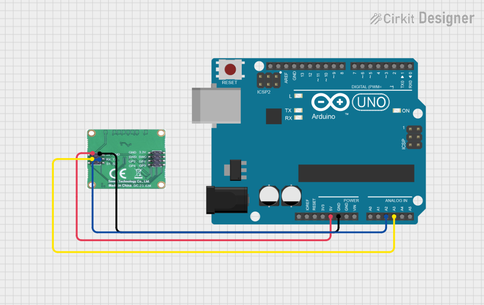
Q: How do I interface the MMWave radar sensor with an Arduino UNO? A: You can interface the sensor using SPI, I2C, or UART, depending on the sensor's capabilities and the available libraries. Ensure you have the correct voltage level conversion if necessary, as the Arduino UNO operates at 5V and the sensor may require 3.3V.
Example Arduino Code
Below is an example of how to initialize communication with a MMWave radar sensor using the I2C protocol on an Arduino UNO. This example assumes the sensor operates at 3.3V and uses a logic level converter for I2C communication.
#include <Wire.h>

// MMWave radar sensor I2C address (check datasheet)
#define SENSOR_I2C_ADDRESS 0xXX

void setup() {
  Wire.begin(); // Initialize I2C communication
  Serial.begin(9600); // Start serial communication for debugging

  // Sensor initialization code here
  // ...
}

void loop() {
  // Code to read data from the sensor
  // ...

  // Example: Request a single byte from the sensor
  Wire.beginTransmission(SENSOR_I2C_ADDRESS);
  Wire.write(0x01); // Register to read (example)
  Wire.endTransmission();
  Wire.requestFrom(SENSOR_I2C_ADDRESS, 1); // Request 1 byte

  if (Wire.available()) {
    byte data = Wire.read(); // Read the byte
    Serial.println(data); // Print the data for debugging
  }

  // Additional processing and loop code here
  // ...
}
Note: The actual initialization and data reading process will depend on the specific MMWave radar sensor model and its communication protocol. Always refer to the manufacturer's datasheet and programming guide for accurate implementation.
Remember to adhere to the 80-character line length limit for code comments, wrapping text as necessary.