How to Use MCP1700-3302E LDO 3.3V: Examples, Pinouts, and Specs
Introduction
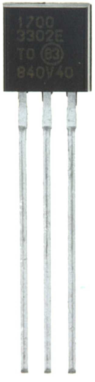
The MCP1700-3302E is a low-dropout (LDO) voltage regulator manufactured by Microchip Technology. It provides a stable output voltage of 3.3V and is specifically designed for low-power applications. With its high accuracy and low quiescent current, the MCP1700-3302E is an excellent choice for battery-powered devices and other energy-sensitive applications.
Explore Projects Built with MCP1700-3302E LDO 3.3V


Explore Projects Built with MCP1700-3302E LDO 3.3V
Common Applications and Use Cases
- Battery-powered devices (e.g., wearables, IoT sensors)
- Microcontroller power supplies
- Portable electronics
- Low-noise analog circuits
- Energy-efficient systems requiring low quiescent current
Technical Specifications
Key Technical Details
| Parameter | Value |
|---|---|
| Output Voltage | 3.3V |
| Input Voltage Range | 2.3V to 6.0V |
| Maximum Output Current | 250 mA |
| Dropout Voltage (typical) | 178 mV at 250 mA |
| Quiescent Current (typical) | 1.6 µA |
| Output Voltage Accuracy | ±0.4% |
| Operating Temperature Range | -40°C to +125°C |
| Package Options | SOT-23-3, SOT-89-3, TO-92 |
Pin Configuration and Descriptions
SOT-23-3 Package
| Pin Number | Name | Description |
|---|---|---|
| 1 | VIN | Input voltage (2.3V to 6.0V) |
| 2 | GND | Ground |
| 3 | VOUT | Regulated output voltage (3.3V) |
TO-92 Package
| Pin Number | Name | Description |
|---|---|---|
| 1 | VOUT | Regulated output voltage (3.3V) |
| 2 | GND | Ground |
| 3 | VIN | Input voltage (2.3V to 6.0V) |
Usage Instructions
How to Use the MCP1700-3302E in a Circuit
- Input Voltage: Connect the input voltage (VIN) to a DC power source within the range of 2.3V to 6.0V. Ensure the input voltage is at least 178 mV higher than the desired 3.3V output for proper regulation.
- Output Voltage: Connect the load to the VOUT pin. The MCP1700-3302E will provide a stable 3.3V output.
- Ground Connection: Connect the GND pin to the circuit ground.
- Capacitors:
- Place a 1 µF ceramic capacitor close to the VIN pin to stabilize the input voltage.
- Place a 1 µF ceramic capacitor close to the VOUT pin to ensure stable output voltage and reduce noise.
Important Considerations and Best Practices
- Thermal Management: Ensure the device operates within its thermal limits, especially when driving high currents. Use proper heat dissipation techniques if necessary.
- Input Voltage Ripple: Minimize input voltage ripple by using a high-quality input capacitor.
- Load Current: Do not exceed the maximum output current of 250 mA to avoid damaging the regulator.
- PCB Layout: Keep the input and output capacitors as close as possible to the MCP1700-3302E to minimize noise and improve stability.
Example: Using MCP1700-3302E with Arduino UNO
The MCP1700-3302E can be used to power an Arduino UNO or other microcontrollers requiring a 3.3V supply. Below is an example circuit and Arduino code to demonstrate its use.
Circuit Diagram
Connect the MCP1700-3302E:
- VIN to a 5V power source (e.g., USB or battery pack).
- VOUT to the 3.3V pin of the Arduino UNO.
- GND to the Arduino's ground.
Add a 1 µF ceramic capacitor between VIN and GND, and another 1 µF ceramic capacitor between VOUT and GND.
Arduino Code Example
// Example code to read an analog sensor powered by MCP1700-3302E
// The sensor is connected to the Arduino's A0 pin.

const int sensorPin = A0; // Analog pin connected to the sensor
int sensorValue = 0;      // Variable to store the sensor reading

void setup() {
  Serial.begin(9600); // Initialize serial communication at 9600 baud
}

void loop() {
  sensorValue = analogRead(sensorPin); // Read the sensor value
  Serial.print("Sensor Value: ");
  Serial.println(sensorValue); // Print the sensor value to the Serial Monitor
  delay(1000); // Wait for 1 second before the next reading
}
Troubleshooting and FAQs
Common Issues and Solutions
No Output Voltage:
- Verify that the input voltage is within the specified range (2.3V to 6.0V).
- Check the connections to ensure VIN, VOUT, and GND are properly connected.
- Ensure the input and output capacitors are correctly placed and have the recommended values.
Output Voltage is Unstable:
- Ensure the output capacitor is a low-ESR ceramic capacitor with a value of at least 1 µF.
- Check for excessive noise or ripple on the input voltage and add filtering if necessary.
Overheating:
- Verify that the load current does not exceed 250 mA.
- Ensure proper thermal management, such as using a heatsink or improving airflow.
Output Voltage is Incorrect:
- Confirm that the MCP1700-3302E part number matches the desired output voltage (3.3V).
- Check for damaged components or incorrect wiring.
FAQs
Q: Can the MCP1700-3302E be used with a 9V battery?
A: No, the maximum input voltage for the MCP1700-3302E is 6.0V. Using a 9V battery would exceed this limit and damage the regulator.
Q: What type of capacitors should I use with the MCP1700-3302E?
A: Use low-ESR ceramic capacitors with a value of at least 1 µF for both input and output.
Q: Can the MCP1700-3302E power a Wi-Fi module?
A: It depends on the current requirements of the Wi-Fi module. The MCP1700-3302E can supply up to 250 mA, so ensure the module's peak current draw does not exceed this limit.
Q: Is the MCP1700-3302E suitable for audio applications?
A: Yes, the MCP1700-3302E's low noise and high accuracy make it suitable for low-noise analog circuits, including audio applications.