
How to Use RP LiDAR C1: Examples, Pinouts, and Specs
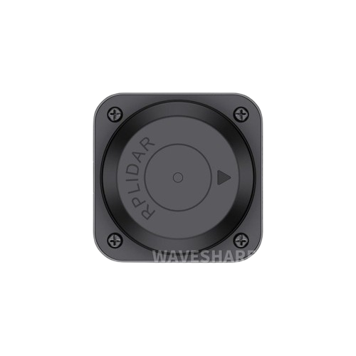
 Design with RP LiDAR C1 in Cirkit Designer
Introduction
The RP LiDAR C1, manufactured by SLAMTEC, is a high-precision LiDAR (Light Detection and Ranging) sensor designed for distance measurement and 3D mapping applications. It is capable of generating detailed topographical data and detecting objects in real-time, making it an essential component for robotics, autonomous navigation, and environmental scanning.
Explore Projects Built with RP LiDAR C1
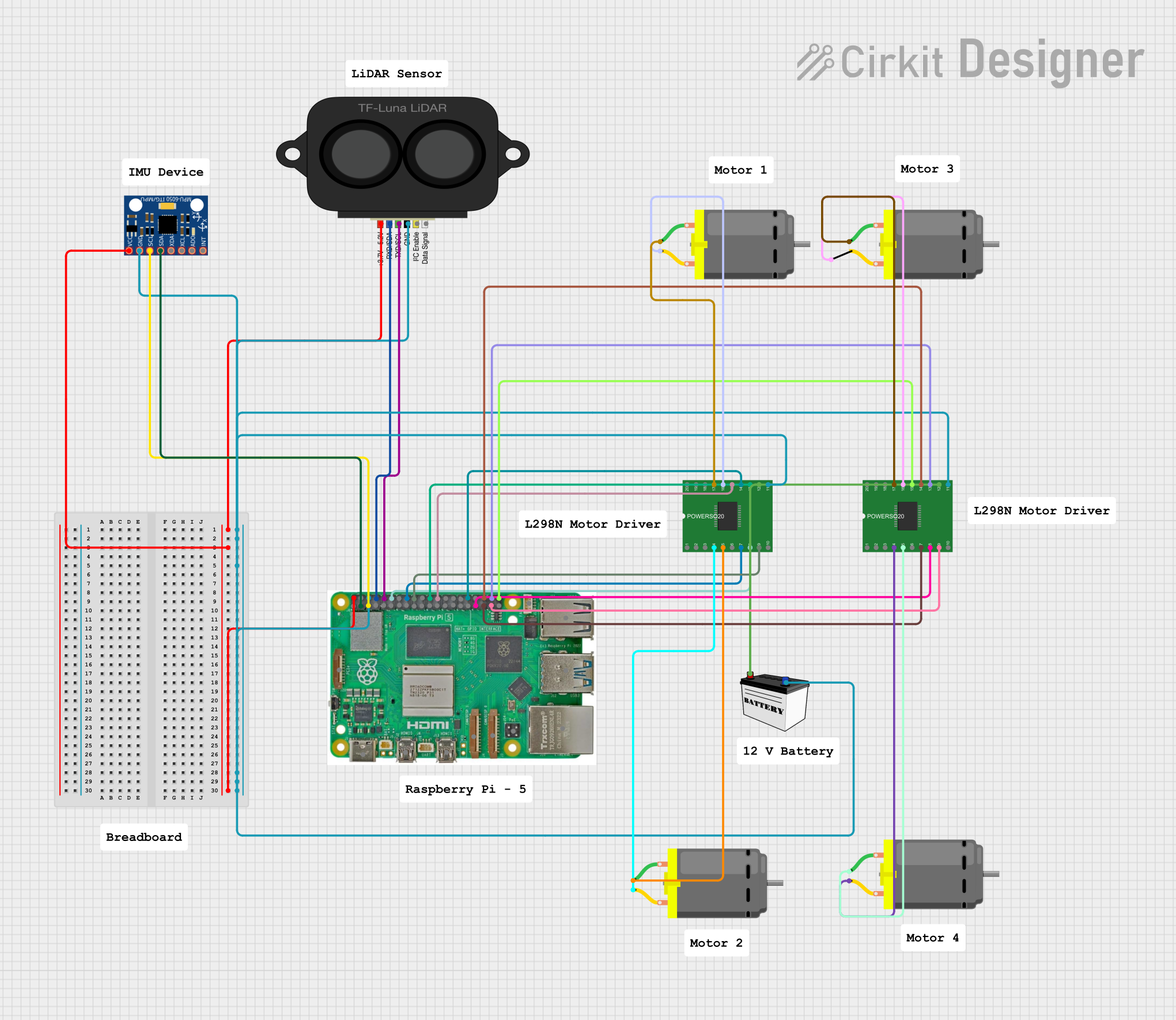 Open Project in Cirkit Designer
 Open Project in Cirkit Designer
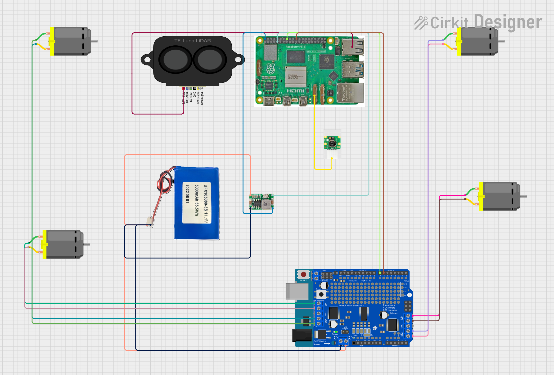 Open Project in Cirkit Designer
 Open Project in Cirkit Designer
Explore Projects Built with RP LiDAR C1
Open Project in Cirkit DesignerOpen Project in Cirkit DesignerOpen Project in Cirkit DesignerOpen Project in Cirkit DesignerCommon Applications and Use Cases
- Autonomous robots and drones for navigation and obstacle avoidance
- 3D mapping and environmental modeling
- Industrial automation and safety systems
- Smart home devices for spatial awareness
- Research and development in robotics and AI
Technical Specifications
The RP LiDAR C1 is engineered for high performance and reliability. Below are its key technical specifications:
| Parameter | Specification |
|---|---|
| Measurement Range | 0.15 m to 25 m |
| Angular Resolution | 0.5° to 1° |
| Scanning Frequency | 5 Hz to 15 Hz |
| Distance Accuracy | ±1% (within 1 m to 10 m range) |
| Operating Voltage | 5 V DC |
| Power Consumption | ≤ 3 W |
| Communication Interface | UART (3.3V TTL) |
| Operating Temperature | -10°C to 40°C |
| Dimensions | 70 mm (diameter) x 41 mm (height) |
| Weight | 190 g |
Pin Configuration and Descriptions
The RP LiDAR C1 uses a standard 5-pin interface for communication and power. Below is the pinout:
| Pin Number | Pin Name | Description |
|---|---|---|
| 1 | VCC | Power input (5 V DC) |
| 2 | GND | Ground |
| 3 | TX | UART Transmit (data output from LiDAR) |
| 4 | RX | UART Receive (data input to LiDAR) |
| 5 | MOTOCTL | Motor control signal (PWM input for motor speed) |
Usage Instructions
How to Use the RP LiDAR C1 in a Circuit
- Power Supply: Connect the VCC pin to a stable 5 V DC power source and the GND pin to ground.
- Communication: Use the TX and RX pins to establish a UART connection with a microcontroller or computer. Ensure the UART voltage levels are compatible (3.3V TTL).
- Motor Control: Use the MOTOCTL pin to control the motor speed. A PWM signal can be applied to adjust the scanning frequency.
- Data Processing: The LiDAR outputs distance and angle data via the UART interface. Use a compatible library or software to parse and process the data.
Important Considerations and Best Practices
- Power Stability: Ensure the power supply is stable and noise-free to avoid measurement inaccuracies.
- Mounting: Mount the LiDAR on a stable platform to minimize vibrations, which can affect accuracy.
- Environment: Avoid using the LiDAR in environments with excessive dust, smoke, or reflective surfaces, as these can interfere with the laser measurements.
- UART Configuration: Set the UART baud rate to the default value of 115200 bps unless otherwise specified in the datasheet or user manual.
- Motor Speed: Adjust the motor speed using the MOTOCTL pin to balance between scanning frequency and data resolution.
Example: Connecting RP LiDAR C1 to Arduino UNO
Below is an example of how to connect and use the RP LiDAR C1 with an Arduino UNO:
Wiring Diagram
| RP LiDAR C1 Pin | Arduino UNO Pin |
|---|---|
| VCC | 5V |
| GND | GND |
| TX | RX (Pin 0) |
| RX | TX (Pin 1) |
| MOTOCTL | PWM Pin (e.g., 9) |
Arduino Code Example
#include <SoftwareSerial.h>

// Define RX and TX pins for SoftwareSerial
SoftwareSerial lidarSerial(10, 11); // RX = Pin 10, TX = Pin 11

void setup() {
  Serial.begin(115200); // Initialize Serial Monitor
  lidarSerial.begin(115200); // Initialize LiDAR UART communication

  pinMode(9, OUTPUT); // Set PWM pin for motor control
  analogWrite(9, 128); // Set motor speed (50% duty cycle)

  Serial.println("RP LiDAR C1 Initialized");
}

void loop() {
  if (lidarSerial.available()) {
    // Read data from LiDAR and forward it to Serial Monitor
    char data = lidarSerial.read();
    Serial.print(data);
  }
}
Notes:
- Use a level shifter if the Arduino operates at 5V logic levels to avoid damaging the LiDAR.
- The motor speed can be adjusted by changing the duty cycle of the PWM signal on Pin 9.
Troubleshooting and FAQs
Common Issues and Solutions
No Data Output from LiDAR
- Cause: Incorrect UART connection or baud rate mismatch.
- Solution: Verify the TX and RX connections and ensure the baud rate is set to 115200 bps.
Inaccurate Distance Measurements
- Cause: Environmental interference (e.g., reflective surfaces or dust).
- Solution: Use the LiDAR in a clean environment and avoid pointing it at highly reflective surfaces.
Motor Not Spinning
- Cause: No PWM signal on the MOTOCTL pin.
- Solution: Check the PWM signal and ensure the duty cycle is set appropriately.
Overheating
- Cause: Prolonged operation in high-temperature environments.
- Solution: Operate the LiDAR within the specified temperature range (-10°C to 40°C).
FAQs
Q: Can the RP LiDAR C1 detect transparent objects?
A: No, the LiDAR may struggle to detect transparent or highly reflective objects due to the nature of laser-based measurements.
Q: What is the maximum scanning frequency?
A: The RP LiDAR C1 supports scanning frequencies up to 15 Hz, adjustable via the MOTOCTL pin.
Q: Is the RP LiDAR C1 compatible with Raspberry Pi?
A: Yes, the LiDAR can be connected to a Raspberry Pi using the UART interface. Ensure proper voltage level conversion if necessary.
Q: How do I parse the data output from the LiDAR?
A: SLAMTEC provides SDKs and libraries for parsing LiDAR data. Alternatively, you can write a custom parser based on the data format specified in the user manual.