
How to Use SCANTOOL: Examples, Pinouts, and Specs
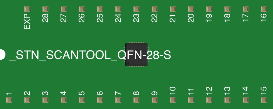
 Design with SCANTOOL in Cirkit Designer
Introduction
A SCANTOOL is a diagnostic tool designed for automotive and electronic applications. It interfaces with a vehicle's onboard computer systems, such as the Engine Control Unit (ECU), to read and interpret diagnostic trouble codes (DTCs), monitor sensor data, and assess system performance. SCANTOOLs are essential for identifying faults, performing maintenance, and optimizing vehicle performance.
Explore Projects Built with SCANTOOL
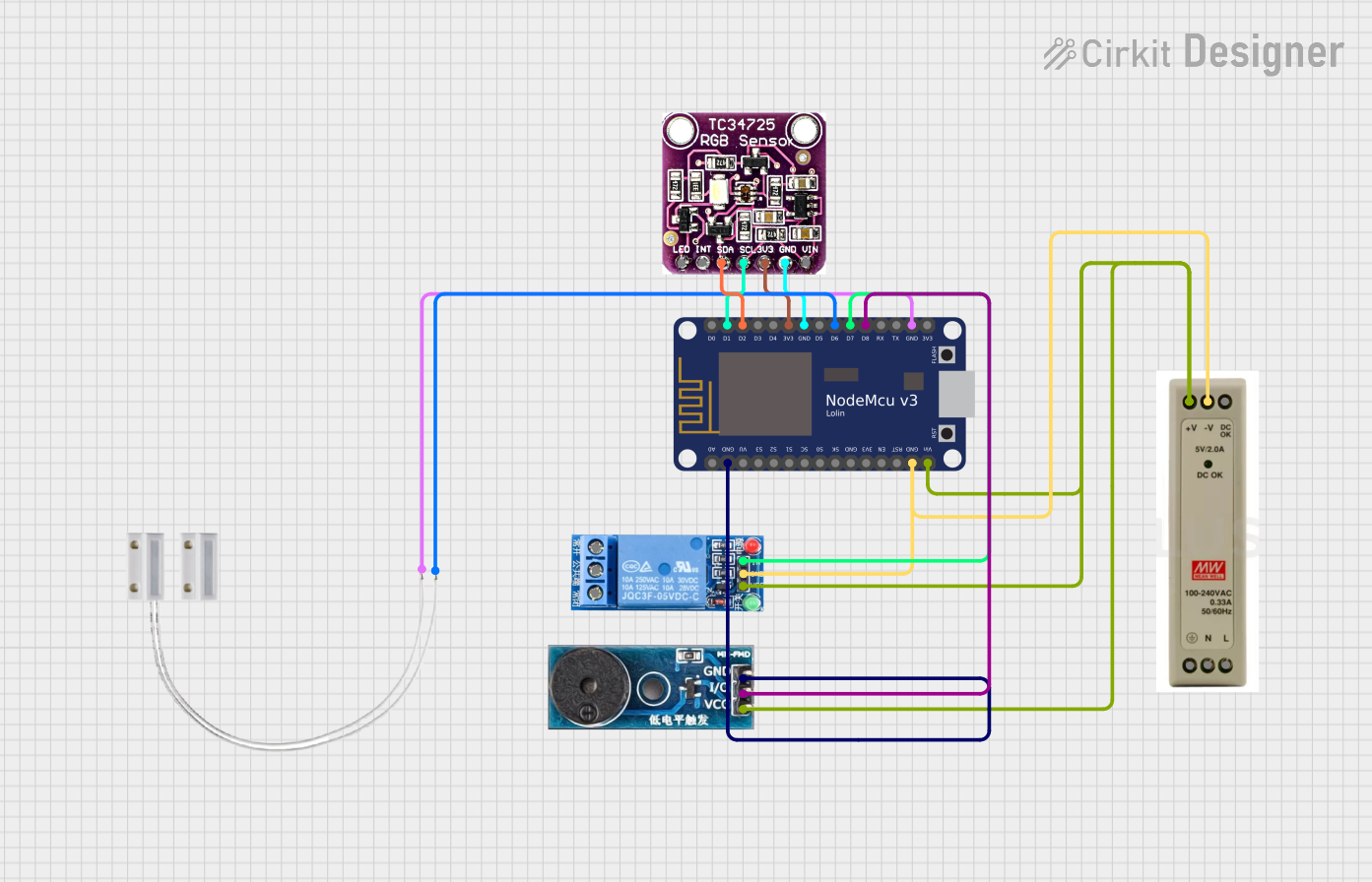 Open Project in Cirkit Designer
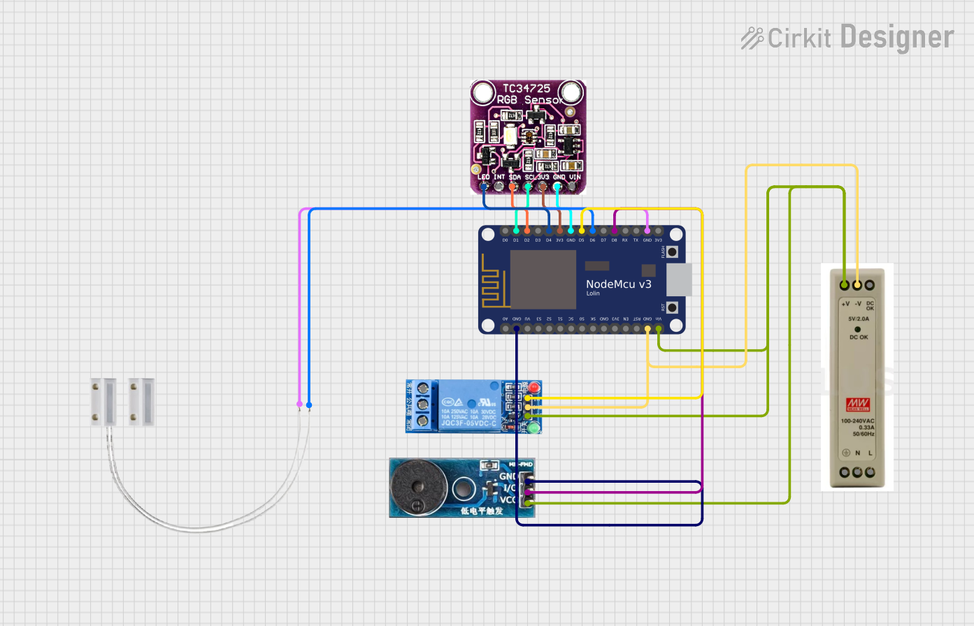 Open Project in Cirkit Designer
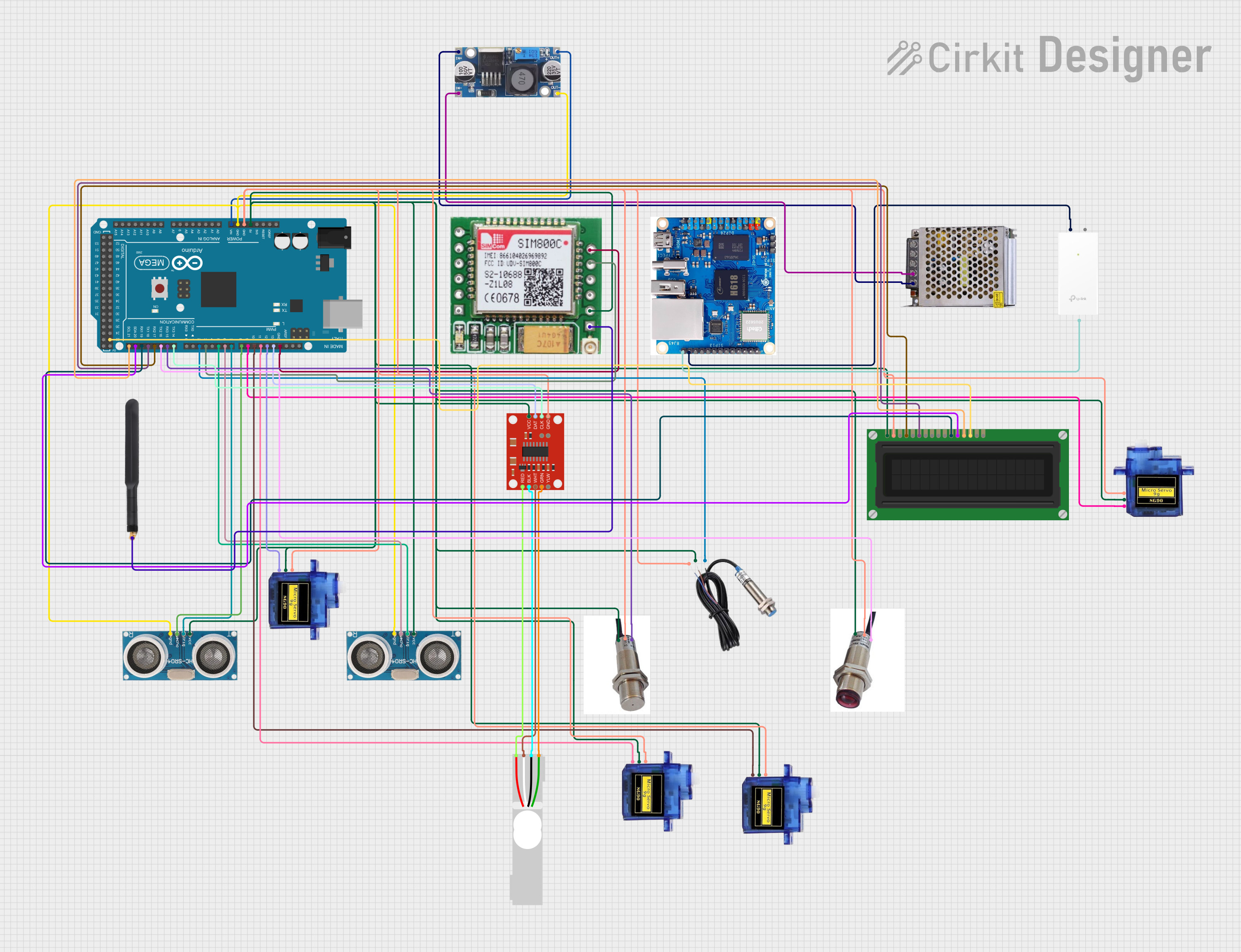 Open Project in Cirkit Designer
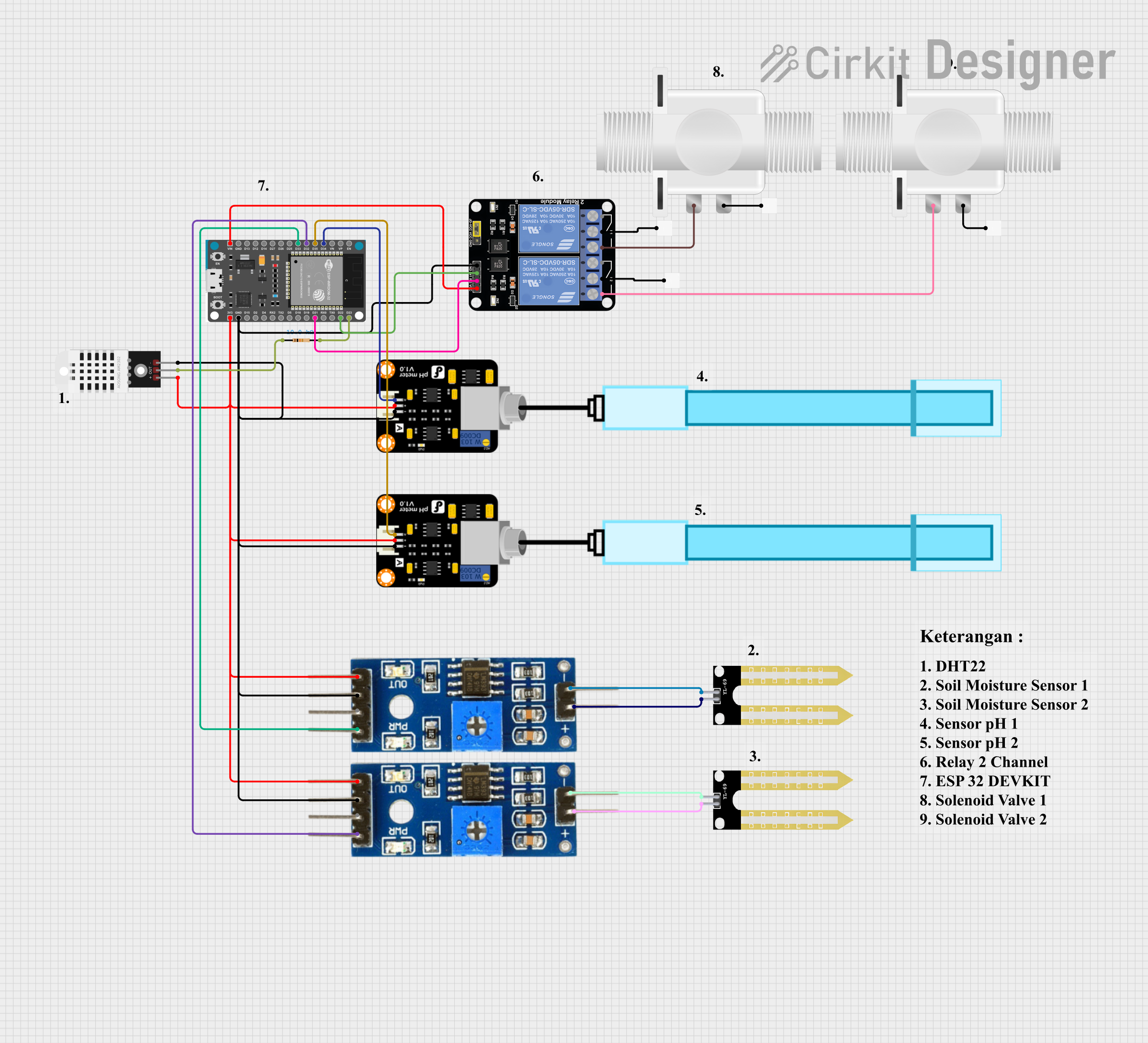 Open Project in Cirkit Designer
Explore Projects Built with SCANTOOL
Open Project in Cirkit DesignerOpen Project in Cirkit DesignerOpen Project in Cirkit DesignerOpen Project in Cirkit DesignerCommon Applications and Use Cases
- Reading and clearing diagnostic trouble codes (DTCs) from the vehicle's ECU.
- Monitoring real-time sensor data, such as engine temperature, RPM, and fuel efficiency.
- Performing emissions tests and ensuring compliance with regulatory standards.
- Resetting service indicators and performing basic maintenance tasks.
- Assisting in troubleshooting and repairing vehicle electronic systems.
Technical Specifications
Below are the general technical specifications for a SCANTOOL. Note that specific models may vary slightly in their features and capabilities.
Key Technical Details
- Communication Protocols: OBD-II (ISO 9141, CAN, KWP2000, J1850 VPW/PWM)
- Operating Voltage: 12V DC (via vehicle OBD-II port)
- Power Consumption: Typically < 2W
- Display: LCD or TFT screen (varies by model)
- Connectivity: USB, Bluetooth, or Wi-Fi (depending on the model)
- Supported Vehicles: OBD-II compliant vehicles (1996 and newer in the U.S.)
- Operating Temperature: -20°C to 70°C (-4°F to 158°F)
Pin Configuration and Descriptions
The SCANTOOL connects to a vehicle's OBD-II port, which has a standardized 16-pin configuration. Below is the pinout for the OBD-II connector:
| Pin Number | Signal Name | Description |
|---|---|---|
| 1 | Manufacturer-Specific | Reserved for OEM-specific functions |
| 2 | J1850 Bus+ | Positive line of the J1850 communication bus |
| 3 | Manufacturer-Specific | Reserved for OEM-specific functions |
| 4 | Chassis Ground | Ground connection for the vehicle chassis |
| 5 | Signal Ground | Ground connection for signal reference |
| 6 | CAN High (J-2284) | High line of the CAN bus |
| 7 | ISO 9141-2 K-Line | K-Line for ISO 9141-2 communication |
| 8 | Manufacturer-Specific | Reserved for OEM-specific functions |
| 9 | Manufacturer-Specific | Reserved for OEM-specific functions |
| 10 | J1850 Bus- | Negative line of the J1850 communication bus |
| 11 | Manufacturer-Specific | Reserved for OEM-specific functions |
| 12 | Manufacturer-Specific | Reserved for OEM-specific functions |
| 13 | Manufacturer-Specific | Reserved for OEM-specific functions |
| 14 | CAN Low (J-2284) | Low line of the CAN bus |
| 15 | ISO 9141-2 L-Line | L-Line for ISO 9141-2 communication |
| 16 | Battery Power | 12V power supply from the vehicle battery |
Usage Instructions
How to Use the SCANTOOL in a Vehicle
- Locate the OBD-II Port: The OBD-II port is typically located under the dashboard near the driver's seat.
- Connect the SCANTOOL: Plug the SCANTOOL into the OBD-II port. Ensure a secure connection.
- Power On the SCANTOOL: Most SCANTOOLs are powered directly by the vehicle's OBD-II port. Turn on the vehicle's ignition (engine off or running, depending on the task).
- Select the Desired Function: Use the SCANTOOL's interface to navigate menus and select functions such as reading DTCs, monitoring live data, or clearing codes.
- Interpret the Data: Refer to the SCANTOOL's manual or online resources to interpret diagnostic codes and sensor data.
- Disconnect Safely: Once diagnostics are complete, turn off the vehicle and unplug the SCANTOOL.
Important Considerations and Best Practices
- Ensure the vehicle is OBD-II compliant before using the SCANTOOL.
- Avoid using the SCANTOOL in extreme temperatures or wet conditions.
- Do not leave the SCANTOOL connected to the vehicle for extended periods to prevent battery drain.
- Regularly update the SCANTOOL's firmware to ensure compatibility with newer vehicles.
- Use caution when clearing DTCs, as this may reset important system data.
Example: Using a SCANTOOL with an Arduino UNO
Some SCANTOOLs with Bluetooth or USB connectivity can interface with an Arduino UNO for custom applications. Below is an example of Arduino code to read data from a SCANTOOL via a serial connection:
#include <SoftwareSerial.h>

// Define RX and TX pins for SoftwareSerial
SoftwareSerial scanToolSerial(10, 11); // RX = pin 10, TX = pin 11

void setup() {
  Serial.begin(9600); // Initialize hardware serial for debugging
  scanToolSerial.begin(9600); // Initialize SCANTOOL serial communication

  Serial.println("SCANTOOL Interface Initialized");
}

void loop() {
  // Check if data is available from the SCANTOOL
  if (scanToolSerial.available()) {
    String data = scanToolSerial.readStringUntil('\n'); // Read data until newline
    Serial.println("Data from SCANTOOL: " + data); // Print data to Serial Monitor
  }

  // Optional: Send commands to the SCANTOOL
  if (Serial.available()) {
    String command = Serial.readStringUntil('\n'); // Read user input
    scanToolSerial.println(command); // Send command to SCANTOOL
  }
}
Note: Ensure the SCANTOOL supports serial communication and is configured to the correct baud rate.
Troubleshooting and FAQs
Common Issues and Solutions
SCANTOOL Does Not Power On
- Cause: Loose connection or faulty OBD-II port.
- Solution: Ensure the SCANTOOL is securely connected to the OBD-II port. Check the vehicle's fuse for the OBD-II port.
Unable to Read Diagnostic Codes
- Cause: Incompatible vehicle or unsupported protocol.
- Solution: Verify that the vehicle is OBD-II compliant and the SCANTOOL supports the required protocol.
Data Displayed is Inaccurate or Incomplete
- Cause: Outdated firmware or poor connection.
- Solution: Update the SCANTOOL's firmware and ensure a secure connection to the OBD-II port.
SCANTOOL Disconnects Frequently
- Cause: Faulty cable or interference (for wireless models).
- Solution: Replace the cable or move the SCANTOOL closer to the vehicle for wireless models.
FAQs
Q: Can I use a SCANTOOL on older vehicles?
A: SCANTOOLs are designed for OBD-II compliant vehicles (1996 and newer in the U.S.). Older vehicles may require specialized diagnostic tools.Q: Is it safe to clear diagnostic trouble codes?
A: Clearing codes is generally safe but may reset system data. Ensure the issue causing the code is resolved before clearing.Q: How do I update the SCANTOOL's firmware?
A: Refer to the manufacturer's instructions. Updates are typically performed via USB or Wi-Fi using a computer or mobile app.Q: Can I use a SCANTOOL while driving?
A: Yes, but only for monitoring live data. Avoid interacting with the SCANTOOL while driving to ensure safety.