Cirkit Designer Logo
Cirkit Designer
Your all-in-one circuit design IDE
Home / 
Component Documentation

How to Use YL-69 Module LM393: Examples, Pinouts, and Specs

Image of YL-69 Module LM393
Cirkit Designer LogoDesign with YL-69 Module LM393 in Cirkit Designer

Introduction

The YL-69 Module LM393 is a soil moisture sensor designed to measure the moisture content of soil, making it an essential tool for agriculture, gardening, and environmental monitoring. The module uses an LM393 comparator to provide a digital output when the soil moisture level crosses a certain threshold, which can be adjusted using an onboard potentiometer. It can also provide an analog output that gives a variable voltage depending on the moisture level.

Explore Projects Built with YL-69 Module LM393

Use Cirkit Designer to design, explore, and prototype these projects online. Some projects support real-time simulation. Click "Open Project" to start designing instantly!
Arduino Nano Based GPS Tracker with GSM Communication and Accelerometer
Image of Circuit Aayush: A project utilizing YL-69 Module LM393 in a practical application
This circuit is designed for communication and location tracking purposes. It features an Arduino Nano interfaced with a SIM800L GSM module for cellular connectivity, a GPS NEO 6M module for obtaining geographical coordinates, and an AITrip ADXL335 GY-61 accelerometer for motion sensing. The LM2596 Step Down Module is used to regulate the power supply to the components.
Cirkit Designer LogoOpen Project in Cirkit Designer
Arduino UNO and LM393-Based Sensor Interface
Image of lm393: A project utilizing YL-69 Module LM393 in a practical application
This circuit consists of an Arduino UNO microcontroller connected to an LM393 comparator. The Arduino provides 5V power and ground to the LM393, and it reads the digital output from the LM393 on pin D7. The provided Arduino code is a basic template with no specific functionality implemented.
Cirkit Designer LogoOpen Project in Cirkit Designer
ESP32 with SIMCOM A7672s IoT Sensor Data Logger
Image of LM393 to LilygoSIM7000: A project utilizing YL-69 Module LM393 in a practical application
This circuit integrates an ESP32 with SIMCOM A7672s module with an LM393 comparator for sensor data acquisition. The ESP32 is programmed to read a digital signal from the LM393's D0 output, corresponding to a threshold detection, and then sends this data to the Blynk Cloud using the SIMCOM A7672s module for remote monitoring. The LM393 is powered by the ESP32's 3.3V supply, and both share a common ground.
Cirkit Designer LogoOpen Project in Cirkit Designer
Arduino GSM Security System with Motion Detection and Light Sensing
Image of Smart Home Security: A project utilizing YL-69 Module LM393 in a practical application
This circuit is designed to interface an Arduino UNO with a SIM800L GSM module, PIR sensor, photocell, buzzer, and multiple LEDs. It is likely intended for environmental monitoring and alerting, with the capability to communicate over GSM for remote notifications. The LM2596 module provides voltage regulation for the GSM module.
Cirkit Designer LogoOpen Project in Cirkit Designer

Explore Projects Built with YL-69 Module LM393

Use Cirkit Designer to design, explore, and prototype these projects online. Some projects support real-time simulation. Click "Open Project" to start designing instantly!
Image of Circuit Aayush: A project utilizing YL-69 Module LM393 in a practical application
Arduino Nano Based GPS Tracker with GSM Communication and Accelerometer
This circuit is designed for communication and location tracking purposes. It features an Arduino Nano interfaced with a SIM800L GSM module for cellular connectivity, a GPS NEO 6M module for obtaining geographical coordinates, and an AITrip ADXL335 GY-61 accelerometer for motion sensing. The LM2596 Step Down Module is used to regulate the power supply to the components.
Cirkit Designer LogoOpen Project in Cirkit Designer
Image of lm393: A project utilizing YL-69 Module LM393 in a practical application
Arduino UNO and LM393-Based Sensor Interface
This circuit consists of an Arduino UNO microcontroller connected to an LM393 comparator. The Arduino provides 5V power and ground to the LM393, and it reads the digital output from the LM393 on pin D7. The provided Arduino code is a basic template with no specific functionality implemented.
Cirkit Designer LogoOpen Project in Cirkit Designer
Image of LM393 to LilygoSIM7000: A project utilizing YL-69 Module LM393 in a practical application
ESP32 with SIMCOM A7672s IoT Sensor Data Logger
This circuit integrates an ESP32 with SIMCOM A7672s module with an LM393 comparator for sensor data acquisition. The ESP32 is programmed to read a digital signal from the LM393's D0 output, corresponding to a threshold detection, and then sends this data to the Blynk Cloud using the SIMCOM A7672s module for remote monitoring. The LM393 is powered by the ESP32's 3.3V supply, and both share a common ground.
Cirkit Designer LogoOpen Project in Cirkit Designer
Image of Smart Home Security: A project utilizing YL-69 Module LM393 in a practical application
Arduino GSM Security System with Motion Detection and Light Sensing
This circuit is designed to interface an Arduino UNO with a SIM800L GSM module, PIR sensor, photocell, buzzer, and multiple LEDs. It is likely intended for environmental monitoring and alerting, with the capability to communicate over GSM for remote notifications. The LM2596 module provides voltage regulation for the GSM module.
Cirkit Designer LogoOpen Project in Cirkit Designer

Common Applications and Use Cases

  • Automated watering systems for plants
  • Soil moisture monitoring in agricultural fields
  • Environmental sensing in smart home systems
  • Educational projects related to plant growth and soil conditions

Technical Specifications

Key Technical Details

  • Operating Voltage: 3.3V to 5V
  • Output Type: Digital (D0) and Analog (A0)
  • Comparator: LM393
  • Sensitivity: Adjustable via onboard potentiometer
  • PCB Size: Approximately 30mm x 16mm

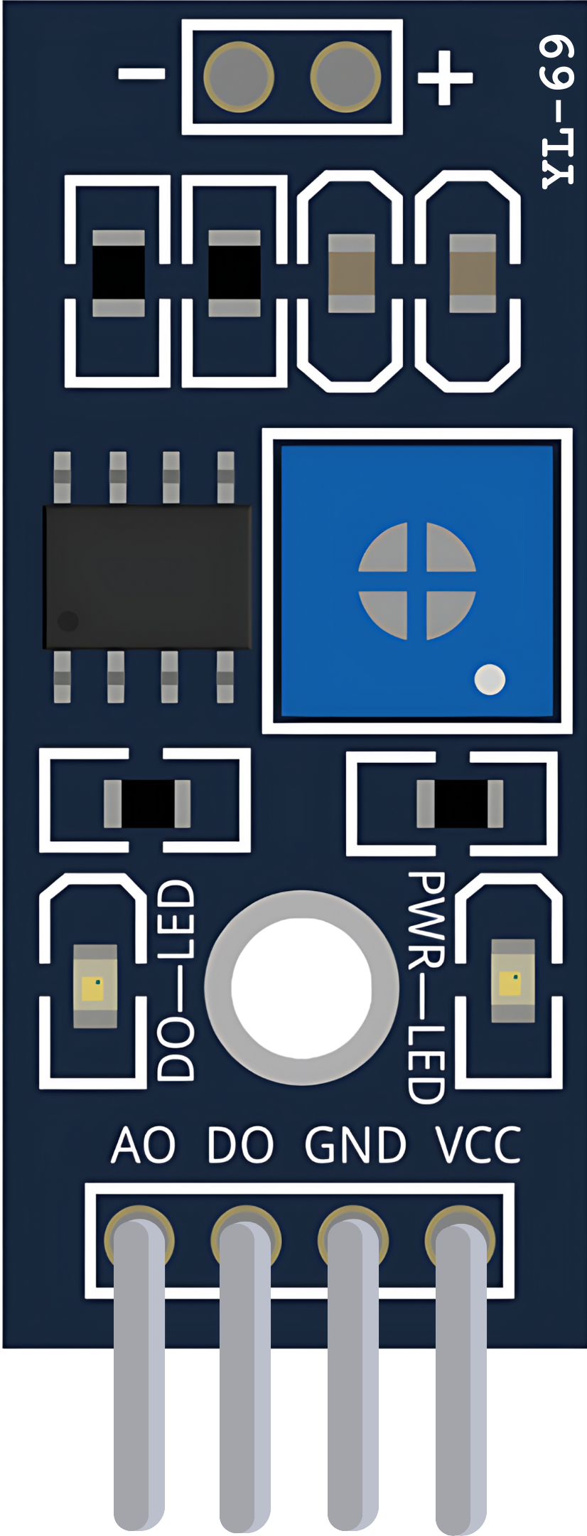
Pin Configuration and Descriptions

Pin Description
VCC Connect to 3.3V-5V power supply
GND Connect to ground
D0 Digital output; goes high or low based on moisture threshold
A0 Analog output; provides a variable voltage related to moisture level

Usage Instructions

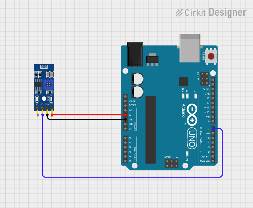
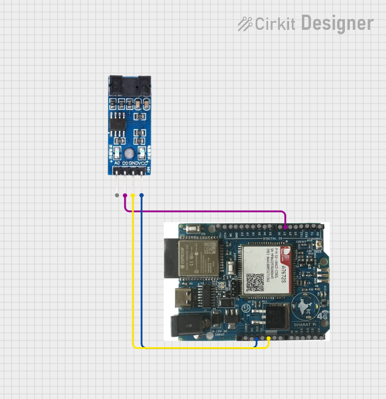
How to Use the Component in a Circuit

  1. Connect the VCC pin to a 3.3V-5V power supply.
  2. Connect the GND pin to the ground of the power supply.
  3. Connect the A0 pin to an analog input of a microcontroller to read the moisture level as an analog value.
  4. Connect the D0 pin to a digital input of a microcontroller if you wish to use the digital output.

Important Considerations and Best Practices

  • Avoid submerging the sensor completely in water to prevent corrosion.
  • Calibrate the sensor by adjusting the onboard potentiometer to set the threshold for the digital output.
  • Use a pull-up resistor if the digital output is left floating.
  • For more accurate readings, take multiple samples and calculate the average.

Example Code for Arduino UNO

// Define the sensor pins
const int analogPin = A0; // Analog output from the sensor
const int digitalPin = 2; // Digital output from the sensor

void setup() {
  Serial.begin(9600);       // Start serial communication at 9600 baud
  pinMode(digitalPin, INPUT); // Set the digital pin as input
}

void loop() {
  int analogValue = analogRead(analogPin); // Read the analog value
  bool isDry = digitalRead(digitalPin);    // Read the digital value

  // Print the analog value to the serial monitor
  Serial.print("Moisture Level (Analog): ");
  Serial.println(analogValue);

  // Print the digital status to the serial monitor
  Serial.print("Is the soil dry? (Digital): ");
  Serial.println(isDry ? "Yes" : "No");

  delay(1000); // Wait for a second before reading again
}

Troubleshooting and FAQs

Common Issues Users Might Face

  • Inconsistent Readings: Ensure that the sensor is inserted into the soil properly and that the soil is uniformly moist.
  • Corrosion of Probes: Minimize the time the sensor is powered to reduce corrosion, and consider waterproofing the sensor.
  • No Output: Check connections and ensure the power supply is within the specified range.

Solutions and Tips for Troubleshooting

  • If the digital output does not change, adjust the onboard potentiometer until the desired threshold is reached.
  • Clean the sensor probes regularly to maintain accuracy.
  • If the sensor is not recognized by the microcontroller, ensure that the correct pins are used and that the board is properly powered.

FAQs

Q: Can the YL-69 Module be used with a 5V system? A: Yes, the module can operate with a 3.3V to 5V power supply.

Q: How do I know if the sensor is working correctly? A: Test the sensor by placing it in dry soil and slowly adding water. The analog value should increase, and the digital output should change when the threshold is crossed.

Q: Is it possible to use the sensor without an Arduino? A: Yes, the sensor can be used with any microcontroller that has analog and digital input pins.

Q: How long do the sensor probes last? A: The lifespan of the probes depends on usage and environmental conditions. Regular cleaning and minimizing exposure to moisture can extend their life.

Q: Can the sensor be left in the soil permanently? A: While the sensor can be left in the soil, prolonged exposure to moisture can lead to corrosion. It's recommended to only power the sensor when measurements are needed.