Cirkit Designer Logo
Cirkit Designer
Your all-in-one circuit design IDE
Home / 
Component Documentation

How to Use E22-400M33S: Examples, Pinouts, and Specs

Image of E22-400M33S
Cirkit Designer LogoDesign with E22-400M33S in Cirkit Designer

Introduction

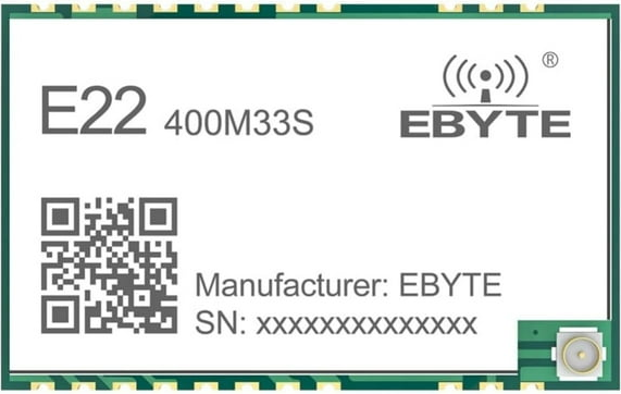
The E22-400M33S is a high-performance RF module manufactured by EByte, based on the SX1268 chipset. This module operates in the 410–493 MHz frequency range and is designed for wireless communication applications. It features a compact design, low power consumption, and long-range communication capabilities, making it ideal for IoT, remote sensing, and telemetry projects.

Explore Projects Built with E22-400M33S

Use Cirkit Designer to design, explore, and prototype these projects online. Some projects support real-time simulation. Click "Open Project" to start designing instantly!
Satellite-Based Timing and Navigation System with SDR and Atomic Clock Synchronization
Image of GPS 시스템 측정 구성도_Confirm: A project utilizing E22-400M33S in a practical application
This circuit appears to be a complex system involving power supply management, GPS and timing synchronization, and data communication. It includes a SI-TEX G1 Satellite Compass for GPS data, an XHTF1021 Atomic Rubidium Clock for precise timing, and Ettus USRP B200 units for software-defined radio communication. Power is supplied through various SMPS units and distributed via terminal blocks and DC jacks. Data communication is facilitated by Beelink MINI S12 N95 computers, RS232 splitters, and a 1000BASE-T Media Converter for network connectivity. RF Directional Couplers are used to interface antennas with the USRP units, and the entire system is likely contained within cases for protection and organization.
Cirkit Designer LogoOpen Project in Cirkit Designer
Satellite Compass and Network-Integrated GPS Data Processing System
Image of GPS 시스템 측정 구성도_241016: A project utilizing E22-400M33S in a practical application
This circuit comprises a satellite compass, a mini PC, two GPS antennas, power supplies, a network switch, media converters, and an atomic rubidium clock. The satellite compass is powered by a triple output DC power supply and interfaces with an RS232 splitter for 1PPS signals. The mini PCs are connected to the USRP B200 devices via USB for data and power, and to media converters via Ethernet, which in turn connect to a network switch using fiber optic links. The antennas are connected to the USRP B200s through RF directional couplers, and the atomic clock provides a 1PPS input to the RS232 splitter.
Cirkit Designer LogoOpen Project in Cirkit Designer
Dual Motor Control System with DPDT Switches and Planetary Gearbox Motors
Image of LEAD SCREW : A project utilizing E22-400M33S in a practical application
This circuit features two DPDT switches that control the direction of two MRB Planetary gearbox motors. The switches are connected to a connector, allowing for external control inputs to change the motor directions.
Cirkit Designer LogoOpen Project in Cirkit Designer
ESP32-Controlled Robotics Interface with AC Synchronous Motor and L298N H-Bridge
Image of Rob1: A project utilizing E22-400M33S in a practical application
This circuit controls a set of MRB Planetary gearbox motors and an AC synchronous motor using an ESP32 microcontroller. The ESP32 interfaces with an L298N Dual H Bridge for motor control and a 1-Channel Relay to switch an AC bulb and the AC synchronous motor. A Mini AC-DC module provides 5V power to the ESP32, the relay, and the servo motor (MG996R), while the main power supply drives the L298N and the gearbox motors.
Cirkit Designer LogoOpen Project in Cirkit Designer

Explore Projects Built with E22-400M33S

Use Cirkit Designer to design, explore, and prototype these projects online. Some projects support real-time simulation. Click "Open Project" to start designing instantly!
Image of GPS 시스템 측정 구성도_Confirm: A project utilizing E22-400M33S in a practical application
Satellite-Based Timing and Navigation System with SDR and Atomic Clock Synchronization
This circuit appears to be a complex system involving power supply management, GPS and timing synchronization, and data communication. It includes a SI-TEX G1 Satellite Compass for GPS data, an XHTF1021 Atomic Rubidium Clock for precise timing, and Ettus USRP B200 units for software-defined radio communication. Power is supplied through various SMPS units and distributed via terminal blocks and DC jacks. Data communication is facilitated by Beelink MINI S12 N95 computers, RS232 splitters, and a 1000BASE-T Media Converter for network connectivity. RF Directional Couplers are used to interface antennas with the USRP units, and the entire system is likely contained within cases for protection and organization.
Cirkit Designer LogoOpen Project in Cirkit Designer
Image of GPS 시스템 측정 구성도_241016: A project utilizing E22-400M33S in a practical application
Satellite Compass and Network-Integrated GPS Data Processing System
This circuit comprises a satellite compass, a mini PC, two GPS antennas, power supplies, a network switch, media converters, and an atomic rubidium clock. The satellite compass is powered by a triple output DC power supply and interfaces with an RS232 splitter for 1PPS signals. The mini PCs are connected to the USRP B200 devices via USB for data and power, and to media converters via Ethernet, which in turn connect to a network switch using fiber optic links. The antennas are connected to the USRP B200s through RF directional couplers, and the atomic clock provides a 1PPS input to the RS232 splitter.
Cirkit Designer LogoOpen Project in Cirkit Designer
Image of LEAD SCREW : A project utilizing E22-400M33S in a practical application
Dual Motor Control System with DPDT Switches and Planetary Gearbox Motors
This circuit features two DPDT switches that control the direction of two MRB Planetary gearbox motors. The switches are connected to a connector, allowing for external control inputs to change the motor directions.
Cirkit Designer LogoOpen Project in Cirkit Designer
Image of Rob1: A project utilizing E22-400M33S in a practical application
ESP32-Controlled Robotics Interface with AC Synchronous Motor and L298N H-Bridge
This circuit controls a set of MRB Planetary gearbox motors and an AC synchronous motor using an ESP32 microcontroller. The ESP32 interfaces with an L298N Dual H Bridge for motor control and a 1-Channel Relay to switch an AC bulb and the AC synchronous motor. A Mini AC-DC module provides 5V power to the ESP32, the relay, and the servo motor (MG996R), while the main power supply drives the L298N and the gearbox motors.
Cirkit Designer LogoOpen Project in Cirkit Designer

Common Applications

  • Internet of Things (IoT) devices
  • Remote sensing and telemetry systems
  • Industrial automation
  • Smart agriculture
  • Wireless sensor networks
  • Home automation

Technical Specifications

Key Specifications

Parameter Value
Frequency Range 410–493 MHz
Modulation LoRa, (G)FSK, (G)MSK
Maximum Output Power 33 dBm (2 W)
Sensitivity -148 dBm
Communication Distance Up to 10 km (line of sight)
Supply Voltage 2.8–5.5 V
Operating Current 120 mA (transmit at 33 dBm)
Sleep Current < 2 µA
Data Rate 0.018–62.5 kbps (LoRa mode)
Operating Temperature -40°C to +85°C
Dimensions 22 × 19 × 3 mm

Pin Configuration

The E22-400M33S module has a total of 8 pins. Below is the pinout and description:

Pin Number Pin Name Description
1 M0 Mode selection pin 0 (used for configuring operating modes)
2 M1 Mode selection pin 1 (used for configuring operating modes)
3 RXD UART receive pin (connect to MCU TXD)
4 TXD UART transmit pin (connect to MCU RXD)
5 AUX Auxiliary pin (indicates module status, e.g., busy or idle)
6 VCC Power supply input (2.8–5.5 V)
7 GND Ground
8 ANT Antenna interface (connect to a 50-ohm antenna for optimal performance)

Usage Instructions

How to Use the E22-400M33S in a Circuit

  1. Power Supply: Connect the VCC pin to a stable power source (2.8–5.5 V) and GND to ground.
  2. UART Communication: Connect the RXD pin to the TXD pin of your microcontroller and the TXD pin to the RXD pin of your microcontroller.
  3. Mode Selection: Use the M0 and M1 pins to configure the module's operating mode:
    • Mode 0 (Normal): M0 = 0, M1 = 0
    • Mode 1 (Wake-up): M0 = 1, M1 = 0
    • Mode 2 (Power-saving): M0 = 0, M1 = 1
    • Mode 3 (Sleep/Configuration): M0 = 1, M1 = 1
  4. Antenna Connection: Attach a 50-ohm antenna to the ANT pin for optimal signal transmission and reception.
  5. Data Transmission: Send and receive data via the UART interface. Ensure the baud rate matches the module's configuration (default: 9600 bps).

Important Considerations

  • Use a decoupling capacitor (e.g., 10 µF) near the VCC pin to stabilize the power supply.
  • Avoid placing the module near high-frequency noise sources to prevent interference.
  • Ensure the antenna is properly matched and positioned for maximum range.
  • Configure the module's parameters (e.g., frequency, power, data rate) using AT commands in configuration mode (Mode 3).

Example: Connecting to an Arduino UNO

Below is an example of how to connect the E22-400M33S to an Arduino UNO and send data.

Wiring Diagram

E22-400M33S Pin Arduino UNO Pin
VCC 5V
GND GND
RXD D3
TXD D2
M0 GND
M1 GND

Arduino Code

#include <SoftwareSerial.h>

// Define RX and TX pins for SoftwareSerial
SoftwareSerial E22Serial(2, 3); // RX = Pin 2, TX = Pin 3

void setup() {
  // Initialize serial communication
  Serial.begin(9600); // For debugging
  E22Serial.begin(9600); // Communication with E22 module

  Serial.println("E22-400M33S Test");
  delay(1000);
}

void loop() {
  // Send data to the E22 module
  E22Serial.println("Hello, E22!");
  Serial.println("Data sent: Hello, E22!");

  // Check for incoming data from the E22 module
  if (E22Serial.available()) {
    String receivedData = E22Serial.readString();
    Serial.print("Data received: ");
    Serial.println(receivedData);
  }

  delay(1000); // Wait 1 second before sending again
}

Troubleshooting and FAQs

Common Issues and Solutions

  1. No Communication with the Module

    • Cause: Incorrect wiring or baud rate mismatch.
    • Solution: Double-check the wiring and ensure the UART baud rate matches the module's configuration.
  2. Short Communication Range

    • Cause: Poor antenna connection or interference.
    • Solution: Ensure the antenna is securely connected and positioned away from interference sources.
  3. Module Not Responding to AT Commands

    • Cause: Module not in configuration mode.
    • Solution: Set M0 and M1 to HIGH (Mode 3) before sending AT commands.
  4. High Power Consumption

    • Cause: Module operating in high-power transmit mode.
    • Solution: Use power-saving mode (Mode 2) when the module is idle.

FAQs

  1. What is the maximum communication distance?

    • The E22-400M33S can achieve up to 10 km in line-of-sight conditions with a proper antenna.
  2. Can I use this module with a 3.3V microcontroller?

    • Yes, the module supports a supply voltage range of 2.8–5.5 V, making it compatible with 3.3V systems.
  3. How do I change the module's frequency or data rate?

    • Use AT commands in configuration mode (Mode 3) to modify parameters such as frequency, power, and data rate.
  4. Is the module compatible with LoRaWAN?

    • No, the E22-400M33S supports LoRa modulation but does not implement the LoRaWAN protocol.

By following this documentation, users can effectively integrate the E22-400M33S into their wireless communication projects.