How to Use Circuit Breaker: Examples, Pinouts, and Specs
Introduction
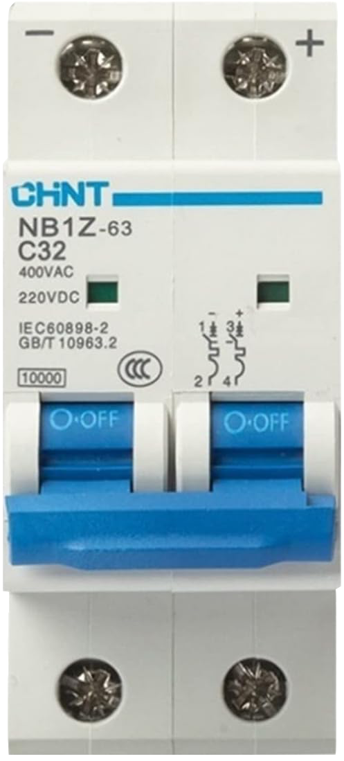
The NIYAKA NB1Z-63 1P C16 is a circuit breaker designed to protect electrical circuits from damage due to excess current resulting from overloads or short circuits. This automatic electrical switch interrupts the flow of current upon fault detection, ensuring safety and preventing potential damage to wiring and devices. Common applications include residential, commercial, and industrial electrical systems where circuit protection is critical.
Explore Projects Built with Circuit Breaker
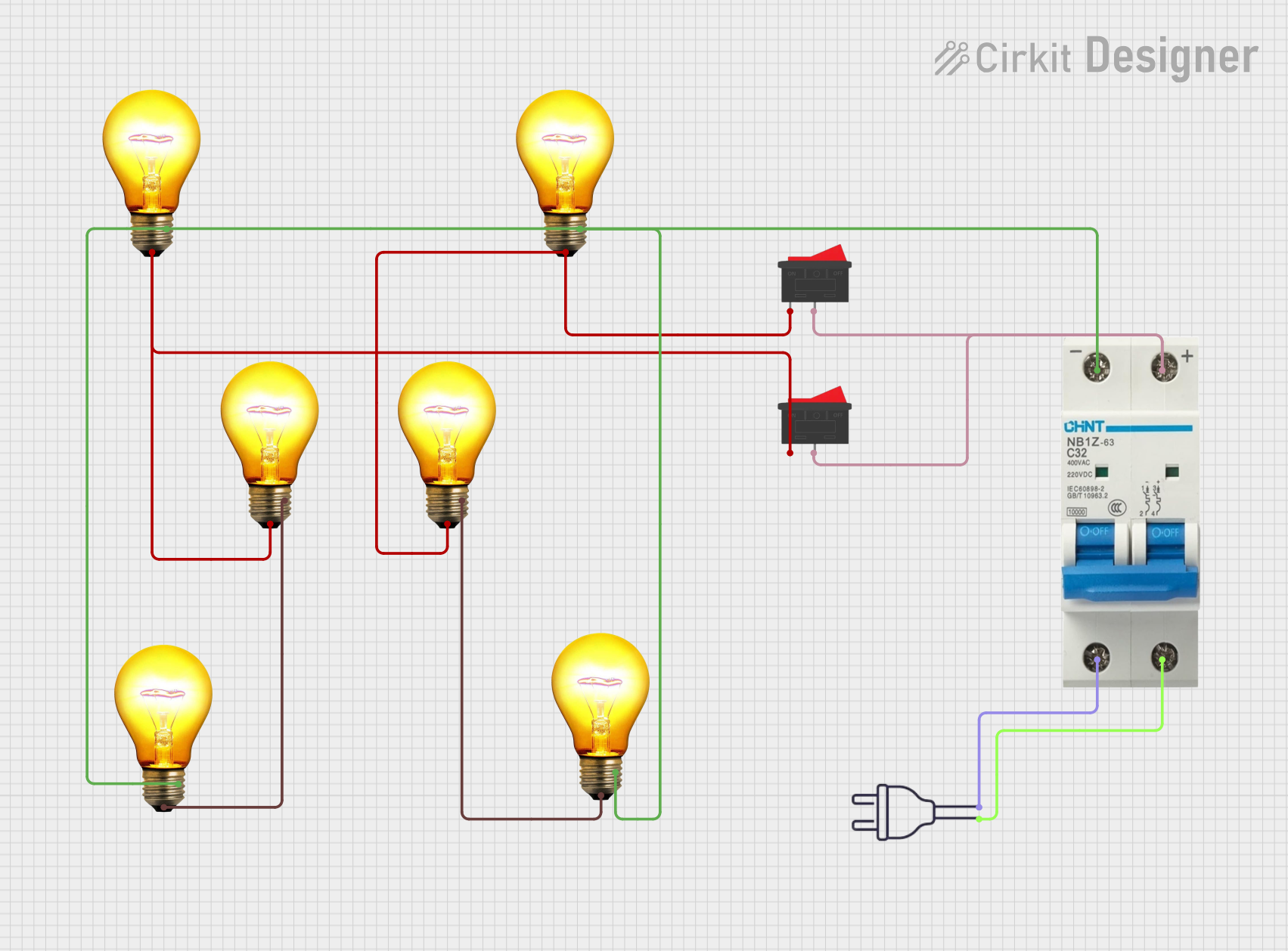
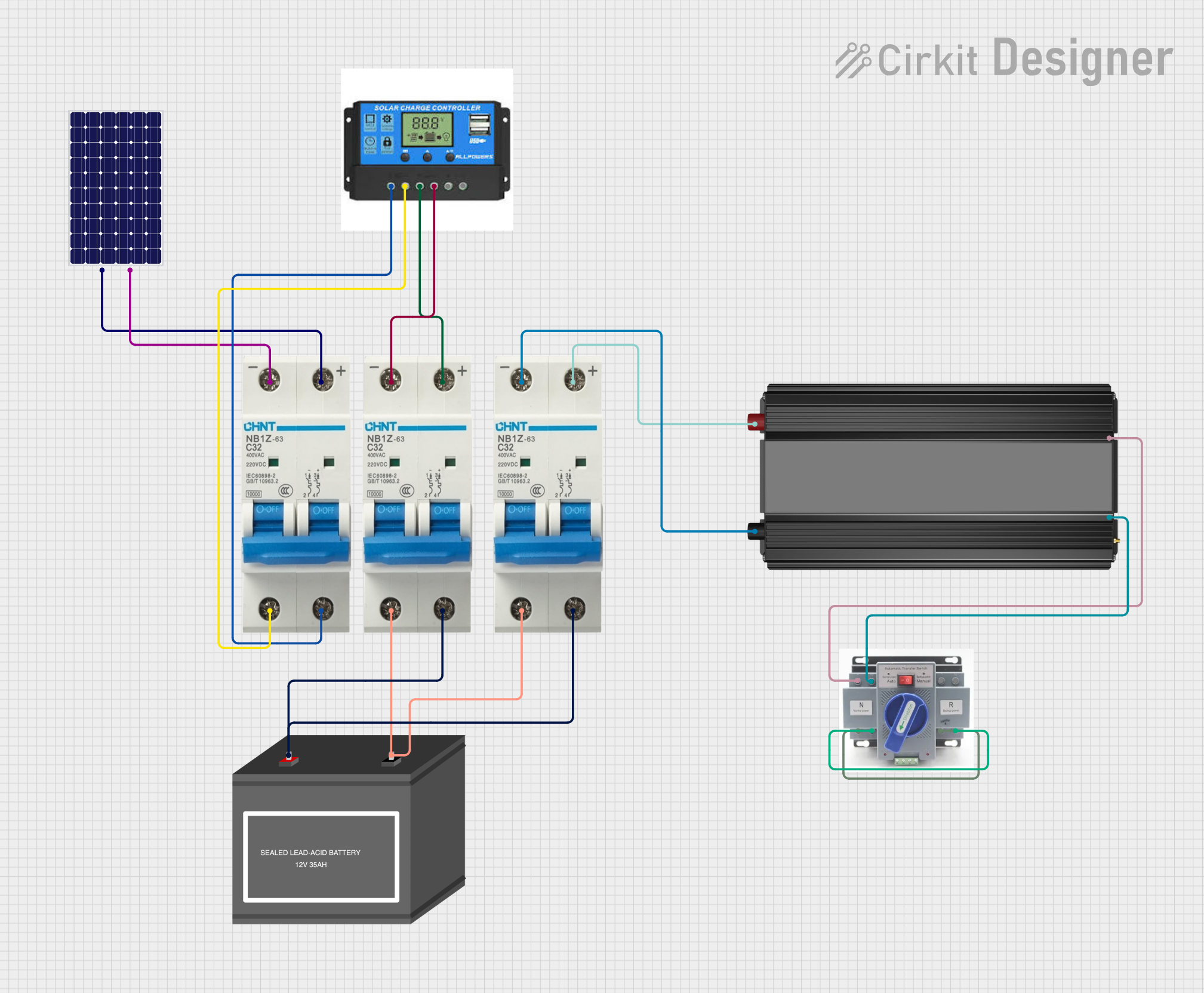

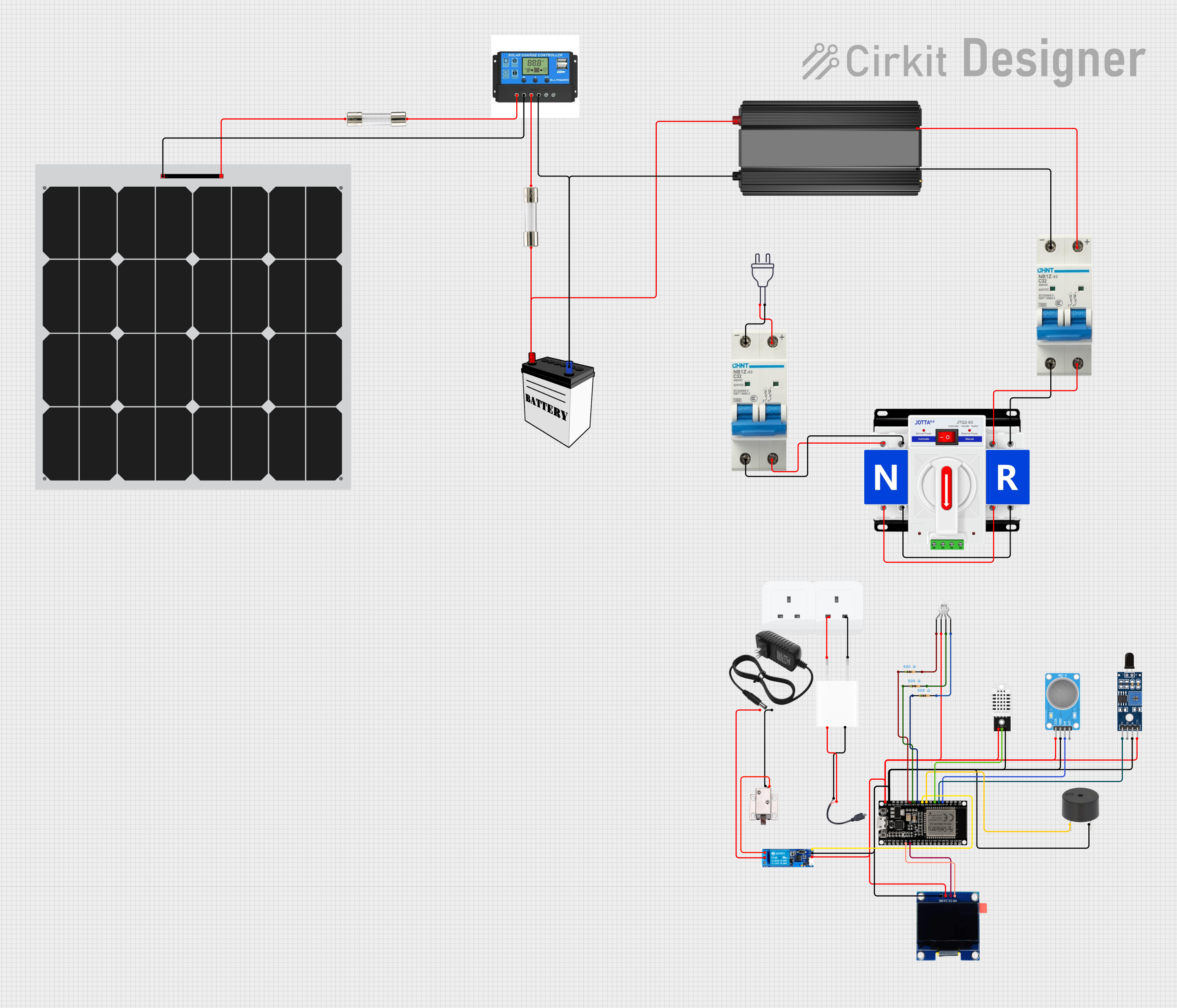
Explore Projects Built with Circuit Breaker
Technical Specifications
General Characteristics
- Manufacturer: NIYAKA
- Part ID: NB1Z-63 1P C16
- Type: Miniature Circuit Breaker (MCB)
- Poles: 1P (Single Pole)
- Tripping Characteristic: C
- Rated Current (In): 16 A
- Rated Voltage (Ue): 230/400V AC
- Breaking Capacity: 6 kA
- Frequency: 50/60 Hz
- Energy Limiting Class: 3
- Ambient Temperature Range: -5°C to +40°C
Pin Configuration and Descriptions
| Pin No. | Description | Notes |
|---|---|---|
| 1 | Line (Power In) | Connect to the upstream supply |
| 2 | Load (Power Out) | Connect to the downstream circuit |
Usage Instructions
Installation
- Power Off: Ensure that the power supply to the circuit where the circuit breaker will be installed is turned off.
- Mounting: Install the circuit breaker onto a DIN rail within the distribution board.
- Wiring: Connect the incoming power line to the terminal labeled '1' and the outgoing line to the terminal labeled '2'.
- Power On: Once securely installed and wired, restore power to the circuit.
Best Practices
- Rating Selection: Choose a circuit breaker with a rated current that matches or exceeds the maximum expected load current but is lower than the cable's current carrying capacity.
- Regular Testing: Periodically test the circuit breaker's trip function to ensure it is operating correctly.
- Environmental Considerations: Install the circuit breaker in an environment within the specified temperature range and protect it from dust and moisture.
Troubleshooting and FAQs
Common Issues
- Circuit Breaker Tripping Frequently: This may indicate an overloaded circuit, a short circuit, or a faulty breaker. Check the connected load and wiring for issues.
- Circuit Breaker Won't Reset: Ensure there is no persistent fault in the circuit and that the breaker is not damaged.
FAQs
Q: Can the NIYAKA NB1Z-63 1P C16 be used for DC applications? A: This circuit breaker is designed for AC applications. Using it for DC circuits is not recommended unless specified by the manufacturer.
Q: What does the 'C' in the tripping characteristic mean? A: The 'C' characteristic indicates that the breaker will trip instantaneously at a current range of 5 to 10 times its rated current, suitable for commercial and industrial applications with moderate inrush currents.
Q: How often should the circuit breaker be tested? A: It is recommended to test the circuit breaker every six months to ensure proper functionality.
Q: What should I do if the circuit breaker does not stay reset? A: If the breaker trips immediately after resetting, disconnect all loads and try again. If it still trips, the breaker may be faulty or there may be a wiring issue.
Code Example for Arduino UNO
While a circuit breaker is not directly interfaced with an Arduino UNO, it can be part of a larger system where the Arduino controls loads that are protected by the circuit breaker. Below is a simple example of how to control a relay connected to a load that should be protected by a circuit breaker.
// Define the relay control pin
const int relayPin = 2;

void setup() {
  // Set the relay control pin as an output
  pinMode(relayPin, OUTPUT);
}

void loop() {
  // Turn on the relay (and the connected load)
  digitalWrite(relayPin, HIGH);
  delay(5000); // Keep the load on for 5 seconds

  // Turn off the relay (and the connected load)
  digitalWrite(relayPin, LOW);
  delay(5000); // Keep the load off for 5 seconds
}
Note: The above code is a basic example and does not include safety features or error handling that would be necessary in a real-world application involving circuit breakers. Always ensure that the relay and the load connected to it do not exceed the circuit breaker's rated current.