How to Use BOARD BTH50015-1LUA: Examples, Pinouts, and Specs
Introduction
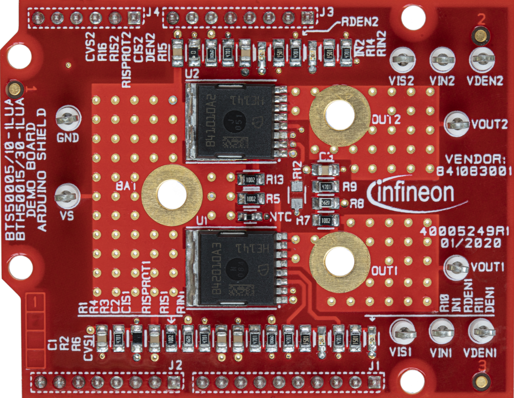
The BOARD BTH50015-1LUA is a printed circuit board (PCB) developed by Infineon. It is designed for specific electronic applications, featuring integrated circuits and components optimized for signal processing and connectivity. This board is ideal for prototyping, testing, and implementing advanced electronic systems.
Explore Projects Built with BOARD BTH50015-1LUA


Explore Projects Built with BOARD BTH50015-1LUA
Common Applications and Use Cases
- Signal processing in communication systems
- IoT (Internet of Things) device development
- Industrial automation and control systems
- Embedded system prototyping
- Educational and research purposes in electronics
Technical Specifications
Key Technical Details
| Parameter | Value |
|---|---|
| Manufacturer | Infineon |
| Part ID | BOARD BTH50015-1LUA |
| Operating Voltage Range | 3.3V to 5V |
| Maximum Current | 500 mA |
| Communication Interfaces | SPI, I2C, UART |
| Dimensions | 50 mm x 50 mm |
| Operating Temperature | -40°C to +85°C |
| PCB Layers | 2 |
Pin Configuration and Descriptions
The BOARD BTH50015-1LUA features a standard pin header for easy integration into various systems. Below is the pin configuration:
| Pin Number | Pin Name | Description |
|---|---|---|
| 1 | VCC | Power supply input (3.3V to 5V) |
| 2 | GND | Ground |
| 3 | SDA | I2C Data Line |
| 4 | SCL | I2C Clock Line |
| 5 | TX | UART Transmit |
| 6 | RX | UART Receive |
| 7 | SPI_MOSI | SPI Master Out Slave In |
| 8 | SPI_MISO | SPI Master In Slave Out |
| 9 | SPI_SCK | SPI Clock |
| 10 | SPI_CS | SPI Chip Select |
| 11 | GPIO1 | General Purpose Input/Output 1 |
| 12 | GPIO2 | General Purpose Input/Output 2 |
Usage Instructions
How to Use the Component in a Circuit
- Power Supply: Connect the VCC pin to a regulated power source (3.3V or 5V) and the GND pin to the ground of your circuit.
- Communication Interface: Choose the appropriate communication protocol (SPI, I2C, or UART) based on your application. Connect the corresponding pins (e.g., SDA/SCL for I2C) to your microcontroller or host device.
- GPIO Pins: Use the GPIO pins for additional control or input/output functionality as required by your application.
- Signal Integrity: Ensure proper decoupling capacitors are placed near the power pins to minimize noise and improve stability.
Important Considerations and Best Practices
- Voltage Compatibility: Ensure the operating voltage of the board matches the voltage levels of your system to avoid damage.
- Pin Connections: Double-check all pin connections to prevent short circuits or incorrect wiring.
- Heat Management: Operate the board within the specified temperature range (-40°C to +85°C) to ensure reliable performance.
- Debugging: Use the UART interface for debugging and monitoring system performance.
Example: Connecting to an Arduino UNO
The BOARD BTH50015-1LUA can be easily interfaced with an Arduino UNO using the I2C protocol. Below is an example code snippet:
#include <Wire.h> // Include the Wire library for I2C communication

#define DEVICE_ADDRESS 0x40 // Replace with the actual I2C address of the board

void setup() {
  Wire.begin(); // Initialize I2C communication
  Serial.begin(9600); // Start serial communication for debugging
  Serial.println("Initializing BOARD BTH50015-1LUA...");
}

void loop() {
  Wire.beginTransmission(DEVICE_ADDRESS); // Start communication with the board
  Wire.write(0x01); // Example: Send a command or data to the board
  Wire.endTransmission(); // End the transmission

  delay(1000); // Wait for 1 second before the next operation
  Serial.println("Command sent to BOARD BTH50015-1LUA.");
}
Troubleshooting and FAQs
Common Issues and Solutions
No Response from the Board
- Cause: Incorrect wiring or power supply issues.
- Solution: Verify all connections, ensure the board is powered correctly, and check the communication protocol settings.
Overheating
- Cause: Operating outside the specified voltage or temperature range.
- Solution: Ensure the input voltage is within 3.3V to 5V and the ambient temperature is within -40°C to +85°C.
Communication Errors
- Cause: Incorrect I2C address or protocol mismatch.
- Solution: Double-check the I2C address and ensure the correct protocol is being used.
FAQs
Q: Can the board operate at 3.3V and 5V interchangeably?
- A: Yes, the board supports both 3.3V and 5V operation. Ensure your system voltage matches the board's input.
Q: What is the maximum data rate for SPI communication?
- A: The maximum SPI clock frequency supported by the board is 10 MHz.
Q: Can I use the GPIO pins for PWM output?
- A: Yes, the GPIO pins can be configured for PWM output depending on your application.
Q: Is the board compatible with Raspberry Pi?
- A: Yes, the board can be interfaced with Raspberry Pi using SPI, I2C, or UART communication protocols.
This concludes the documentation for the BOARD BTH50015-1LUA. For further assistance, refer to the manufacturer's datasheet or contact Infineon support.