
How to Use MX1508 Driver: Examples, Pinouts, and Specs
 Design with MX1508 Driver in Cirkit Designer
Introduction
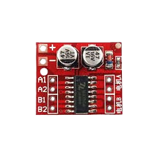
The MX1508 Dual DC Motor Driver Module is a compact and efficient motor driver designed for controlling two DC motors or a single stepper motor. It features a dual H-bridge configuration, allowing for bidirectional control of motor direction and speed using Pulse Width Modulation (PWM) signals. This module is widely used in robotics, automation, and DIY electronics projects due to its simplicity and versatility.
Explore Projects Built with MX1508 Driver
 Open Project in Cirkit Designer
 Open Project in Cirkit Designer
 Open Project in Cirkit Designer
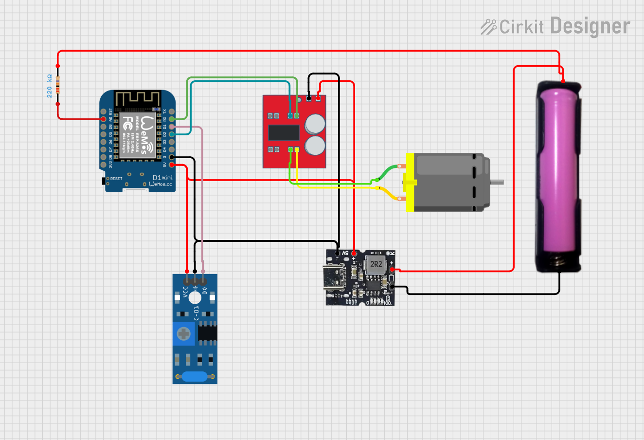 Open Project in Cirkit Designer
Explore Projects Built with MX1508 Driver
Open Project in Cirkit DesignerOpen Project in Cirkit DesignerOpen Project in Cirkit DesignerOpen Project in Cirkit DesignerCommon Applications
- Robotics (e.g., motorized robots, robotic arms)
- Automated systems (e.g., conveyor belts, smart cars)
- DIY projects involving DC or stepper motors
- Educational kits for learning motor control
Technical Specifications
The following table outlines the key technical details of the MX1508 module:
| Parameter | Value |
|---|---|
| Operating Voltage | 2.0V to 10.0V |
| Output Current (per channel) | 1.5A (continuous), 2.5A (peak) |
| Control Signal Voltage | 1.8V to 7.0V |
| PWM Frequency | Up to 20 kHz |
| Number of Channels | 2 (dual H-bridge) |
| Dimensions | 24mm x 21mm x 5mm |
| Weight | ~3g |
Pin Configuration and Descriptions
The MX1508 module has 8 pins, as described in the table below:
| Pin | Name | Description |
|---|---|---|
| 1 | VCC | Power supply input (2.0V to 10.0V). Connect to the positive terminal of the power source. |
| 2 | GND | Ground connection. Connect to the negative terminal of the power source. |
| 3 | INA1 | Input signal for Motor A direction control. High/Low logic level. |
| 4 | INB1 | Input signal for Motor A direction control. High/Low logic level. |
| 5 | INA2 | Input signal for Motor B direction control. High/Low logic level. |
| 6 | INB2 | Input signal for Motor B direction control. High/Low logic level. |
| 7 | OUT1 | Output terminal for Motor A. Connect to one terminal of Motor A. |
| 8 | OUT2 | Output terminal for Motor B. Connect to one terminal of Motor B. |
Usage Instructions
How to Use the MX1508 in a Circuit
- Power Supply: Connect the VCC pin to a power source (2.0V to 10.0V) and the GND pin to ground.
- Motor Connections:
- Connect the terminals of Motor A to OUT1 and OUT2.
- For a second motor (Motor B), connect its terminals to OUT3 and OUT4.
- Control Signals:
- Use INA1 and INB1 to control the direction and speed of Motor A.
- Use INA2 and INB2 to control the direction and speed of Motor B.
- Apply PWM signals to these pins to adjust motor speed.
- Logic Voltage: Ensure the control signals are within the range of 1.8V to 7.0V.
Example Arduino Code
Below is an example of how to control two DC motors using the MX1508 module and an Arduino UNO:
// Define motor control pins
const int INA1 = 3; // Motor A direction pin 1
const int INB1 = 5; // Motor A direction pin 2
const int INA2 = 6; // Motor B direction pin 1
const int INB2 = 9; // Motor B direction pin 2

void setup() {
  // Set motor control pins as outputs
  pinMode(INA1, OUTPUT);
  pinMode(INB1, OUTPUT);
  pinMode(INA2, OUTPUT);
  pinMode(INB2, OUTPUT);
}

void loop() {
  // Example: Rotate Motor A forward at 50% speed
  analogWrite(INA1, 128); // PWM signal (0-255) for speed control
  analogWrite(INB1, 0);   // Set INB1 to LOW for forward direction

  // Example: Rotate Motor B backward at 75% speed
  analogWrite(INA2, 0);   // Set INA2 to LOW for backward direction
  analogWrite(INB2, 192); // PWM signal (0-255) for speed control

  delay(2000); // Run motors for 2 seconds

  // Stop both motors
  analogWrite(INA1, 0);
  analogWrite(INB1, 0);
  analogWrite(INA2, 0);
  analogWrite(INB2, 0);

  delay(2000); // Wait for 2 seconds before repeating
}
Important Considerations
- Power Supply: Ensure the power supply voltage matches the motor's requirements and does not exceed the module's maximum voltage (10V).
- Heat Dissipation: The module may heat up during operation. Use a heat sink or ensure proper ventilation if operating at high currents.
- PWM Frequency: Use a PWM frequency below 20 kHz for optimal performance.
Troubleshooting and FAQs
Common Issues and Solutions
Motors Not Spinning:
- Check the power supply connections to ensure proper voltage and polarity.
- Verify that the control signals (INAx and INBx) are correctly configured.
- Ensure the motor connections to OUT1/OUT2 (or OUT3/OUT4) are secure.
Motor Spins in the Wrong Direction:
- Swap the INA and INB signals for the affected motor to reverse its direction.
- Alternatively, reverse the motor's wiring at the output terminals.
Module Overheating:
- Reduce the motor load or operating current.
- Add a heat sink or improve ventilation around the module.
PWM Control Not Working:
- Ensure the PWM signal is within the supported frequency range (up to 20 kHz).
- Verify that the Arduino or microcontroller is correctly configured to output PWM signals.
FAQs
Q: Can the MX1508 drive stepper motors?
A: Yes, the MX1508 can drive a single stepper motor by controlling its coils through the dual H-bridge configuration. However, additional logic may be required for precise step control.
Q: What is the maximum current the module can handle?
A: The MX1508 can handle up to 1.5A continuous current per channel and 2.5A peak current.
Q: Can I use a 12V power supply with this module?
A: No, the maximum operating voltage for the MX1508 is 10V. Using a 12V power supply may damage the module.
Q: Is the module compatible with 3.3V logic?
A: Yes, the MX1508 supports control signal voltages as low as 1.8V, making it compatible with 3.3V and 5V logic systems.