How to Use PIC: Examples, Pinouts, and Specs
Introduction
The PIC18F45K22 is a high-performance 8-bit microcontroller from Microchip Technology's PIC family. It is designed for embedded applications requiring efficient control, low power consumption, and robust functionality. This microcontroller is equipped with advanced features such as multiple timers, analog-to-digital converters (ADCs), and communication interfaces, making it suitable for a wide range of applications.
Explore Projects Built with PIC
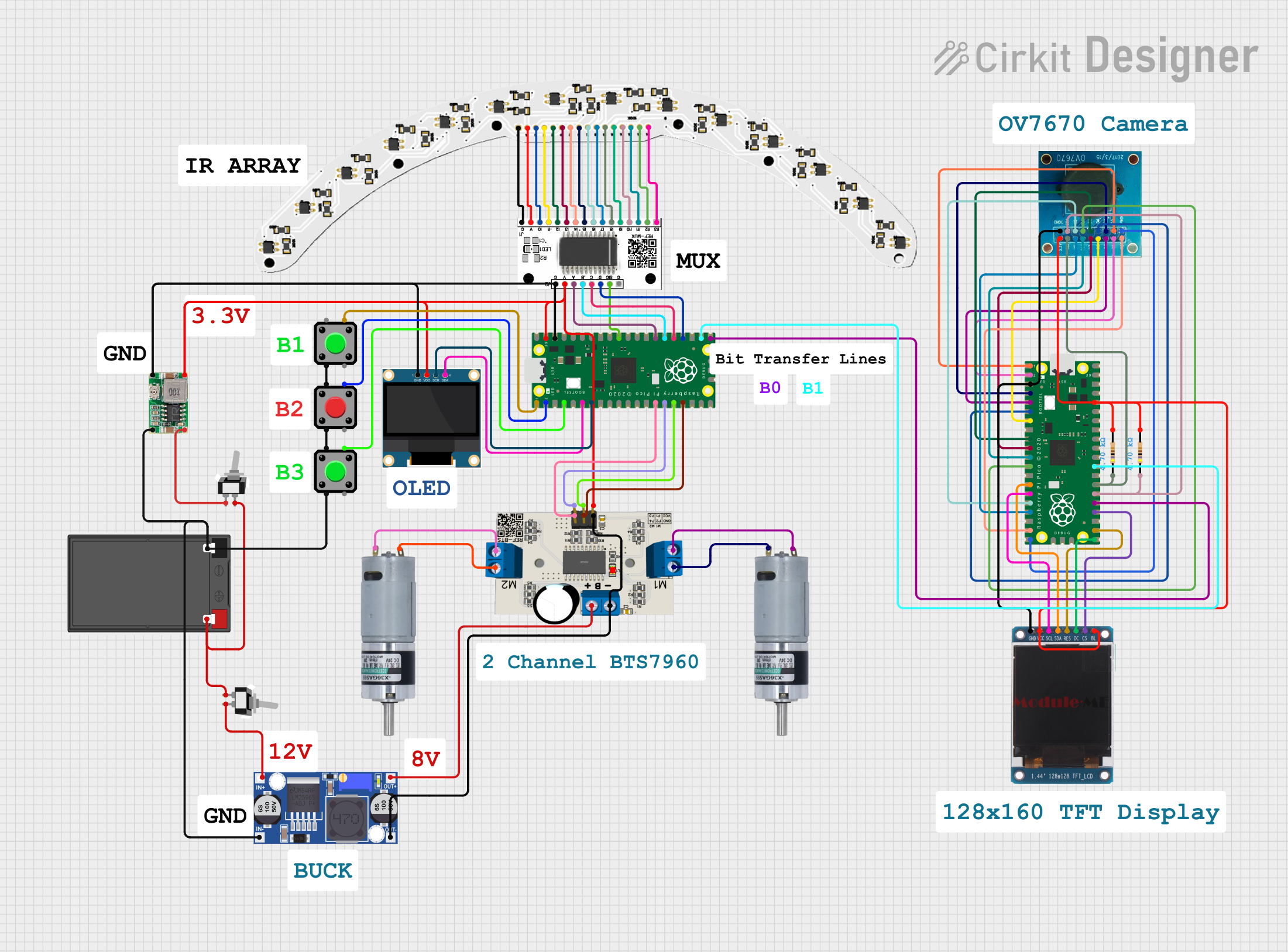

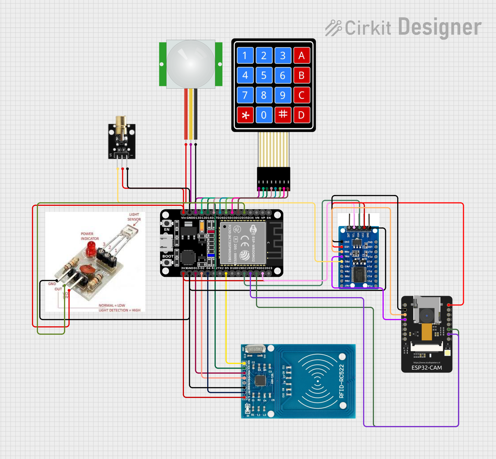
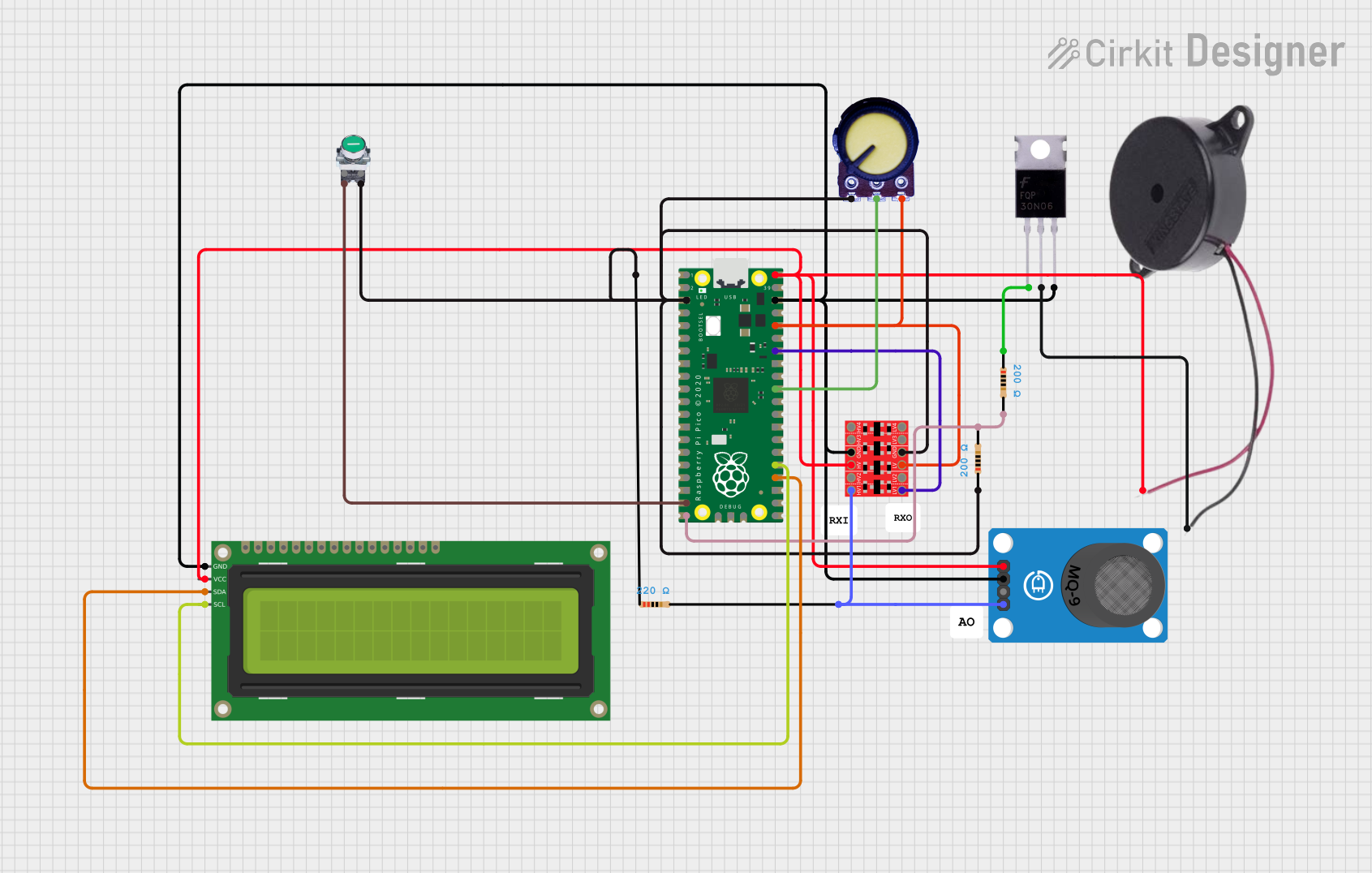
Explore Projects Built with PIC
Common Applications
- Home automation systems
- Industrial control systems
- Consumer electronics
- Data acquisition systems
- Motor control and robotics
- IoT (Internet of Things) devices
Technical Specifications
The PIC18F45K22 microcontroller offers a rich set of features to meet the needs of various embedded applications. Below are its key technical specifications:
General Features
- Core Architecture: 8-bit PIC
- Operating Voltage: 1.8V to 5.5V
- Program Memory: 64 KB Flash
- RAM: 3,968 bytes
- EEPROM: 1,024 bytes
- Clock Speed: Up to 64 MHz (16 MIPS)
- Package Options: 40-pin PDIP, 44-pin TQFP, 44-pin QFN
Peripherals
- Timers: 3 x 16-bit timers, 1 x 8-bit timer
- ADC: 10-bit ADC with up to 30 channels
- PWM: Enhanced CCP (Capture/Compare/PWM) modules
- Communication Interfaces:
- 2 x EUSART (UART)
- 2 x SPI
- 2 x I²C
- Comparators: 2 analog comparators
- Watchdog Timer: Yes, with programmable period
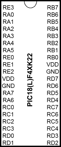
Pin Configuration
The PIC18F45K22 has 40 pins in the PDIP package. Below is the pin configuration and description for key pins:
| Pin Number | Pin Name | Function |
|---|---|---|
| 1 | MCLR/VPP | Master Clear (Reset) / Programming Voltage |
| 2-5, 7-8, 10-13, 15-18 | RA0-RA7 | Port A: Digital I/O, ADC inputs |
| 6 | VSS | Ground |
| 9 | VDD | Power Supply |
| 19-22, 24-27 | RB0-RB7 | Port B: Digital I/O, Interrupt-on-Change |
| 23 | VSS | Ground |
| 28-35 | RC0-RC7 | Port C: Digital I/O, Communication Interfaces |
| 36-39 | RD0-RD3 | Port D: Digital I/O |
| 40 | VDD | Power Supply |
For a complete pinout, refer to the official datasheet.
Usage Instructions
The PIC18F45K22 is versatile and can be used in a variety of circuits. Below are the steps and best practices for using this microcontroller:
Basic Circuit Setup
- Power Supply: Connect the VDD pin to a regulated power source (1.8V to 5.5V) and the VSS pin to ground.
- Reset Pin: Connect the MCLR pin to VDD through a 10kΩ pull-up resistor. Optionally, add a push-button switch to ground for manual reset.
- Oscillator: Connect an external crystal oscillator (e.g., 16 MHz) between the OSC1 and OSC2 pins, along with appropriate capacitors (typically 22pF) to ground.
- Programming: Use an ICSP (In-Circuit Serial Programming) header to program the microcontroller using a compatible programmer (e.g., Microchip PICkit 4).
Example: Blinking an LED with Arduino UNO
The PIC18F45K22 can be programmed using MPLAB X IDE and XC8 compiler. Below is an example code to blink an LED connected to pin RB0:
// Include the header file for the PIC18F45K22
#include <xc.h>

// Configuration bits: Set up the oscillator and other settings
#pragma config FOSC = INTIO67  // Internal oscillator block
#pragma config WDTEN = OFF    // Watchdog Timer disabled
#pragma config LVP = OFF      // Low-Voltage Programming disabled

// Define the clock frequency for delay calculations
#define _XTAL_FREQ 16000000  // 16 MHz internal oscillator

void main(void) {
    TRISBbits.TRISB0 = 0;  // Set RB0 as output
    LATBbits.LATB0 = 0;    // Initialize RB0 to LOW

    while (1) {
        LATBbits.LATB0 = 1;  // Turn on LED
        __delay_ms(500);     // Delay for 500 ms
        LATBbits.LATB0 = 0;  // Turn off LED
        __delay_ms(500);     // Delay for 500 ms
    }
}
Best Practices
- Use decoupling capacitors (e.g., 0.1µF) near the VDD and VSS pins to reduce noise.
- Avoid leaving unused pins floating; configure them as outputs or connect them to ground.
- Use proper pull-up or pull-down resistors for input pins to ensure stable operation.
Troubleshooting and FAQs
Common Issues
Microcontroller Not Responding
- Cause: Incorrect power supply or missing decoupling capacitors.
- Solution: Verify the power supply voltage and add 0.1µF capacitors near the VDD and VSS pins.
Programming Failure
- Cause: Incorrect ICSP connections or configuration bits.
- Solution: Double-check the ICSP connections and ensure the configuration bits are set correctly in the code.
Unstable Operation
- Cause: Missing or incorrect oscillator configuration.
- Solution: Verify the external crystal oscillator and capacitor values. Alternatively, use the internal oscillator.
FAQs
Q: Can the PIC18F45K22 operate without an external oscillator?
A: Yes, it has an internal oscillator that can operate up to 16 MHz. However, for precise timing, an external oscillator is recommended.
Q: How do I protect the microcontroller from accidental resets?
A: Use a pull-up resistor (10kΩ) on the MCLR pin and avoid placing the reset button in a noisy environment.
Q: Can I use the PIC18F45K22 for low-power applications?
A: Yes, it supports multiple power-saving modes, including Sleep mode, to reduce power consumption.
For more detailed information, refer to the official Microchip PIC18F45K22 datasheet.