How to Use 0.96" 4-pin OLED Display: Examples, Pinouts, and Specs
Introduction
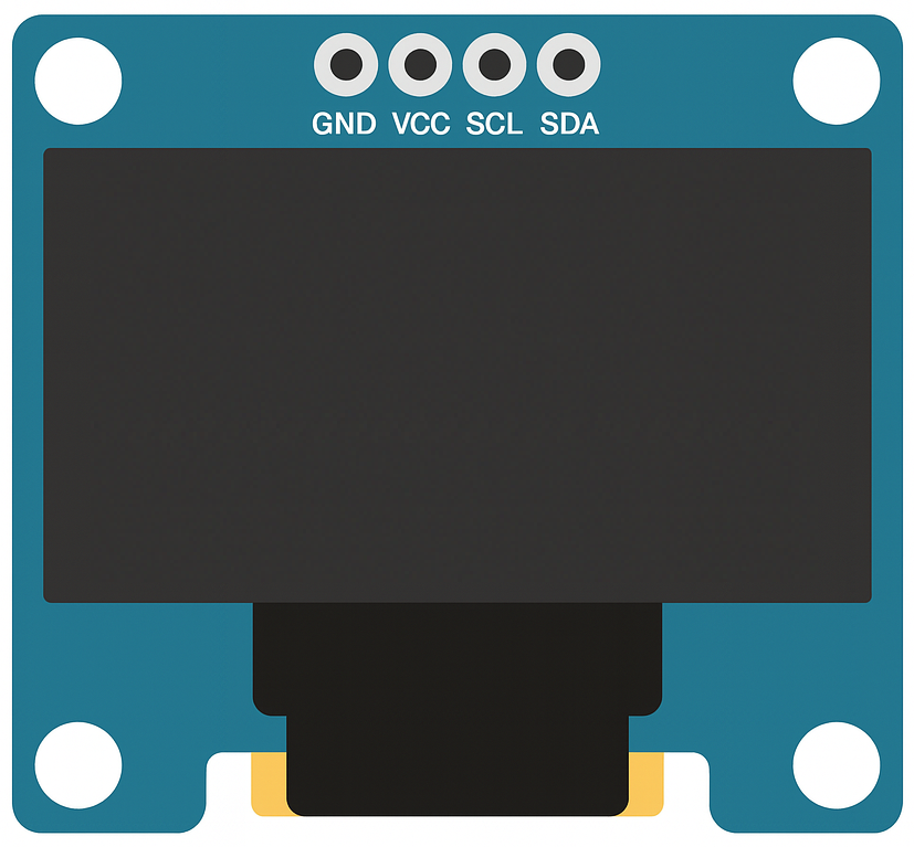
The 0.96" 4-pin OLED Display is a compact, low-power display module that utilizes organic light-emitting diodes (OLEDs) to produce bright, high-contrast, and vibrant images. With a resolution of 128x64 pixels, this display is ideal for applications requiring clear visuals in a small form factor. Its 4-pin interface simplifies integration with microcontrollers, making it a popular choice for hobbyists, students, and professionals alike.
Explore Projects Built with 0.96" 4-pin OLED Display


Explore Projects Built with 0.96" 4-pin OLED Display
Common Applications and Use Cases
- Wearable devices and smart gadgets
- IoT (Internet of Things) projects
- Portable electronics and handheld devices
- Data visualization for sensors and microcontroller projects
- User interfaces for embedded systems
Technical Specifications
Key Technical Details
| Parameter | Specification |
|---|---|
| Display Type | OLED (Organic Light-Emitting Diode) |
| Resolution | 128x64 pixels |
| Display Size | 0.96 inches (diagonal) |
| Interface | I2C (Inter-Integrated Circuit) |
| Operating Voltage | 3.3V to 5V |
| Operating Current | ~20mA |
| Viewing Angle | >160° |
| Driver IC | SSD1306 |
| Communication Speed | Up to 400kHz (I2C Fast Mode) |
| Operating Temperature | -40°C to +85°C |
Pin Configuration and Descriptions
| Pin Name | Pin Number | Description |
|---|---|---|
| GND | 1 | Ground pin. Connect to the ground of the power supply. |
| VCC | 2 | Power supply pin. Connect to 3.3V or 5V. |
| SCL | 3 | I2C clock line. Connect to the SCL pin of the microcontroller. |
| SDA | 4 | I2C data line. Connect to the SDA pin of the microcontroller. |
Usage Instructions
How to Use the Component in a Circuit
- Power the Display: Connect the
VCCpin to a 3.3V or 5V power source and theGNDpin to the ground. - Connect I2C Lines:
- Connect the
SCLpin to the I2C clock line of your microcontroller. - Connect the
SDApin to the I2C data line of your microcontroller.
- Connect the
- Pull-Up Resistors: Ensure that the I2C lines (SCL and SDA) have pull-up resistors (typically 4.7kΩ to 10kΩ) if not already present on the microcontroller board.
- Install Required Libraries: For Arduino, install the
Adafruit_GFXandAdafruit_SSD1306libraries via the Arduino Library Manager. - Write Code: Use the libraries to initialize and control the display.
Important Considerations and Best Practices
- Voltage Compatibility: Ensure the display's operating voltage matches your microcontroller's I2C voltage level (3.3V or 5V).
- I2C Address: The default I2C address for most 0.96" OLED displays is
0x3C. Verify this in the datasheet or by scanning I2C devices. - Avoid Static Damage: Handle the display carefully to avoid damage from electrostatic discharge (ESD).
- Brightness Control: Prolong the lifespan of the OLED by reducing brightness when full intensity is not required.
Example Code for Arduino UNO
#include <Wire.h>
#include <Adafruit_GFX.h>
#include <Adafruit_SSD1306.h>

// Define the OLED display width and height
#define SCREEN_WIDTH 128
#define SCREEN_HEIGHT 64

// Create an SSD1306 display object connected via I2C
Adafruit_SSD1306 display(SCREEN_WIDTH, SCREEN_HEIGHT, &Wire, -1);

void setup() {
  // Initialize serial communication for debugging
  Serial.begin(9600);

  // Initialize the OLED display
  if (!display.begin(SSD1306_I2C_ADDRESS, 0x3C)) {
    // If initialization fails, print an error message
    Serial.println(F("SSD1306 allocation failed"));
    for (;;); // Halt the program
  }

  // Clear the display buffer
  display.clearDisplay();

  // Display a welcome message
  display.setTextSize(1); // Set text size
  display.setTextColor(SSD1306_WHITE); // Set text color
  display.setCursor(0, 0); // Set cursor position
  display.println(F("Hello, OLED!")); // Print text
  display.display(); // Update the display
  delay(2000); // Wait for 2 seconds
}

void loop() {
  // Clear the display buffer
  display.clearDisplay();

  // Draw a rectangle
  display.drawRect(10, 10, 50, 30, SSD1306_WHITE);

  // Display the rectangle
  display.display();

  // Wait for 1 second
  delay(1000);
}
Troubleshooting and FAQs
Common Issues and Solutions
Display Not Turning On:
- Verify the power connections (
VCCandGND). - Ensure the I2C address matches the display's default address (
0x3Cor0x3D).
- Verify the power connections (
No Output on the Display:
- Check the I2C connections (
SCLandSDA) for proper wiring. - Use an I2C scanner sketch to confirm the display is detected on the I2C bus.
- Check the I2C connections (
Flickering or Unstable Display:
- Ensure proper pull-up resistors are present on the I2C lines.
- Check for loose or poor-quality connections.
Text or Graphics Not Displaying Correctly:
- Verify that the correct resolution (128x64) is set in the code.
- Ensure the
Adafruit_GFXandAdafruit_SSD1306libraries are up to date.
FAQs
Q: Can I use this display with a 3.3V microcontroller?
A: Yes, the display is compatible with both 3.3V and 5V systems.
Q: What is the lifespan of the OLED display?
A: The typical lifespan is around 10,000 to 50,000 hours, depending on brightness and usage.
Q: Can I use this display with SPI instead of I2C?
A: No, this specific 4-pin OLED display is designed for I2C communication only. For SPI, consider a different model.
Q: How do I reduce power consumption?
A: Lower the brightness or turn off the display when not in use to save power.