How to Use 20A 10-60V PWM Speed Controller: Examples, Pinouts, and Specs
Introduction
The 20A 10-60V PWM Speed Controller is a versatile and efficient device designed to regulate the speed of DC motors by utilizing Pulse Width Modulation (PWM) technology. By adjusting the duty cycle of the PWM signal, this controller allows precise control over motor speed without significant energy loss. It is suitable for DC motors operating within a voltage range of 10V to 60V and can handle currents up to 20A, making it ideal for a wide range of applications.
Explore Projects Built with 20A 10-60V PWM Speed Controller


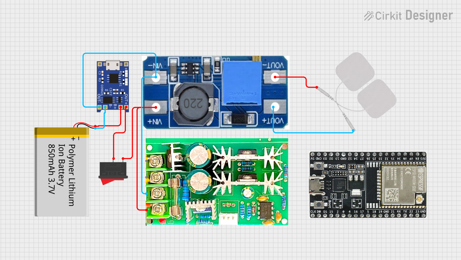
Explore Projects Built with 20A 10-60V PWM Speed Controller
Common Applications and Use Cases
- Electric vehicles (e.g., scooters, e-bikes)
- Conveyor belts and industrial automation
- DIY robotics and hobby projects
- Fans, pumps, and other motor-driven devices
- Solar-powered systems requiring motor control
Technical Specifications
The following table outlines the key technical details of the 20A 10-60V PWM Speed Controller:
| Parameter | Specification |
|---|---|
| Manufacturer | Generic |
| Part ID | 20A PWM Speed Controller |
| Input Voltage Range | 10V - 60V DC |
| Maximum Current | 20A |
| PWM Frequency | 15 kHz |
| Duty Cycle Range | 0% - 100% |
| Efficiency | ≥ 90% |
| Operating Temperature | -20°C to 60°C |
| Dimensions | 60mm x 40mm x 28mm |
| Weight | ~50g |
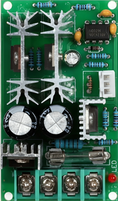
Pin Configuration and Descriptions
The 20A 10-60V PWM Speed Controller typically features the following terminals for connection:
| Pin/Terminal | Label | Description |
|---|---|---|
| 1 | VIN+ | Positive input voltage terminal (connect to the positive terminal of the power supply). |
| 2 | VIN- | Negative input voltage terminal (connect to the negative terminal of the power supply). |
| 3 | MOTOR+ | Positive output terminal (connect to the positive terminal of the DC motor). |
| 4 | MOTOR- | Negative output terminal (connect to the negative terminal of the DC motor). |
| 5 | Potentiometer | Speed control knob for adjusting the PWM duty cycle (0% to 100%). |
Usage Instructions
How to Use the Component in a Circuit
Power Supply Connection:
- Connect the positive terminal of your DC power supply to the
VIN+terminal. - Connect the negative terminal of your DC power supply to the
VIN-terminal. - Ensure the input voltage is within the range of 10V to 60V DC.
- Connect the positive terminal of your DC power supply to the
Motor Connection:
- Connect the positive terminal of your DC motor to the
MOTOR+terminal. - Connect the negative terminal of your DC motor to the
MOTOR-terminal.
- Connect the positive terminal of your DC motor to the
Speed Adjustment:
- Use the built-in potentiometer to adjust the motor speed. Turning the knob clockwise increases the speed, while turning it counterclockwise decreases the speed.
Testing:
- Power on the system and gradually adjust the potentiometer to test the motor's response.
- Monitor the motor's performance to ensure it operates within safe voltage and current limits.
Important Considerations and Best Practices
- Current Limitation: Ensure the motor's current draw does not exceed 20A to prevent damage to the controller.
- Heat Dissipation: The controller may generate heat during operation. Use proper ventilation or a heatsink if necessary.
- Polarity: Double-check the polarity of all connections to avoid damage to the controller or motor.
- Fuse Protection: Consider adding a fuse between the power supply and the controller for additional safety.
- Avoid Overvoltage: Do not exceed the maximum input voltage of 60V DC.
Example: Using with an Arduino UNO
While the 20A 10-60V PWM Speed Controller has a built-in potentiometer for manual control, it can also be controlled via an Arduino UNO by replacing the potentiometer with a PWM signal. Below is an example code snippet:
// Example code to control the 20A PWM Speed Controller using Arduino UNO
// Connect the Arduino PWM pin (e.g., D9) to the PWM input of the controller

const int pwmPin = 9; // PWM output pin connected to the controller

void setup() {
  pinMode(pwmPin, OUTPUT); // Set the PWM pin as an output
}

void loop() {
  // Gradually increase motor speed
  for (int dutyCycle = 0; dutyCycle <= 255; dutyCycle++) {
    analogWrite(pwmPin, dutyCycle); // Write PWM signal to the controller
    delay(20); // Wait 20ms before increasing the duty cycle
  }

  // Gradually decrease motor speed
  for (int dutyCycle = 255; dutyCycle >= 0; dutyCycle--) {
    analogWrite(pwmPin, dutyCycle); // Write PWM signal to the controller
    delay(20); // Wait 20ms before decreasing the duty cycle
  }
}
Troubleshooting and FAQs
Common Issues and Solutions
Motor Does Not Start:
- Cause: Incorrect wiring or insufficient input voltage.
- Solution: Verify all connections and ensure the input voltage is within the specified range.
Controller Overheats:
- Cause: Excessive current draw or poor ventilation.
- Solution: Ensure the motor's current draw does not exceed 20A. Use a heatsink or fan for cooling.
Motor Speed is Unstable:
- Cause: Noise or interference in the power supply.
- Solution: Use a filtered power supply or add capacitors to reduce noise.
Potentiometer Does Not Adjust Speed:
- Cause: Faulty potentiometer or loose connection.
- Solution: Check the potentiometer connections and replace it if necessary.
FAQs
Q: Can this controller reverse the motor direction?
A: No, this controller does not support reversing motor direction. Use an H-bridge circuit for bidirectional control.Q: Can I use this controller with a 24V battery system?
A: Yes, the controller supports input voltages between 10V and 60V, so a 24V system is compatible.Q: Is it safe to use this controller outdoors?
A: The controller is not waterproof. If used outdoors, ensure it is enclosed in a weatherproof housing.Q: Can I control multiple motors with this controller?
A: No, this controller is designed to control a single motor. Use separate controllers for multiple motors.
This concludes the documentation for the 20A 10-60V PWM Speed Controller.