How to Use ILI9341 4.0 inch: Examples, Pinouts, and Specs
Introduction
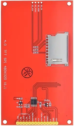
The ILI9341 4.0-inch TFT LCD display module is a versatile and compact display solution designed for embedded systems and microcontroller-based projects. Manufactured in China, this module features a 240x320 pixel resolution and utilizes the ILI9341 driver IC for efficient control and rendering of graphical content. Its vibrant color display and touch functionality (if supported by the specific variant) make it ideal for applications requiring visual output, such as user interfaces, data visualization, and gaming.
Explore Projects Built with ILI9341 4.0 inch


Explore Projects Built with ILI9341 4.0 inch
Common Applications and Use Cases
- Embedded systems requiring graphical user interfaces (GUIs)
- DIY electronics projects and prototyping
- Industrial control panels
- Portable devices and handheld instruments
- Educational projects and hobbyist applications
Technical Specifications
The following table outlines the key technical details of the ILI9341 4.0-inch TFT LCD module:
| Parameter | Specification |
|---|---|
| Display Type | TFT LCD |
| Driver IC | ILI9341 |
| Screen Size | 4.0 inches |
| Resolution | 240x320 pixels |
| Color Depth | 16-bit (65,536 colors) |
| Interface | SPI (Serial Peripheral Interface) |
| Operating Voltage | 3.3V (logic level) |
| Backlight Voltage | 3.3V to 5V |
| Current Consumption | ~50mA (typical, with backlight on) |
| Operating Temperature | -20°C to 70°C |
| Dimensions | ~71mm x 52mm x 7mm |
Pin Configuration and Descriptions
The ILI9341 module typically features an 8-pin or 10-pin interface for SPI communication. Below is the pinout description:
| Pin | Name | Description |
|---|---|---|
| 1 | VCC | Power supply input (3.3V or 5V, depending on the module variant). |
| 2 | GND | Ground connection. |
| 3 | CS | Chip Select (active low). Used to enable communication with the display. |
| 4 | RESET | Reset pin. Resets the display when pulled low. |
| 5 | DC (RS) | Data/Command control pin. High for data, low for command. |
| 6 | SDI (MOSI) | Serial Data Input (Master Out Slave In). Transfers data to the display. |
| 7 | SCK | Serial Clock. Synchronizes data transfer. |
| 8 | LED | Backlight control. Connect to 3.3V or 5V for backlight operation. |
| 9 | SDO (MISO) | Serial Data Output (optional, used for SPI read operations). |
| 10 | T_IRQ | Touch interrupt pin (if touch functionality is supported). |
Note: Pin names and configurations may vary slightly depending on the specific module variant. Always refer to the datasheet or documentation provided with your module.
Usage Instructions
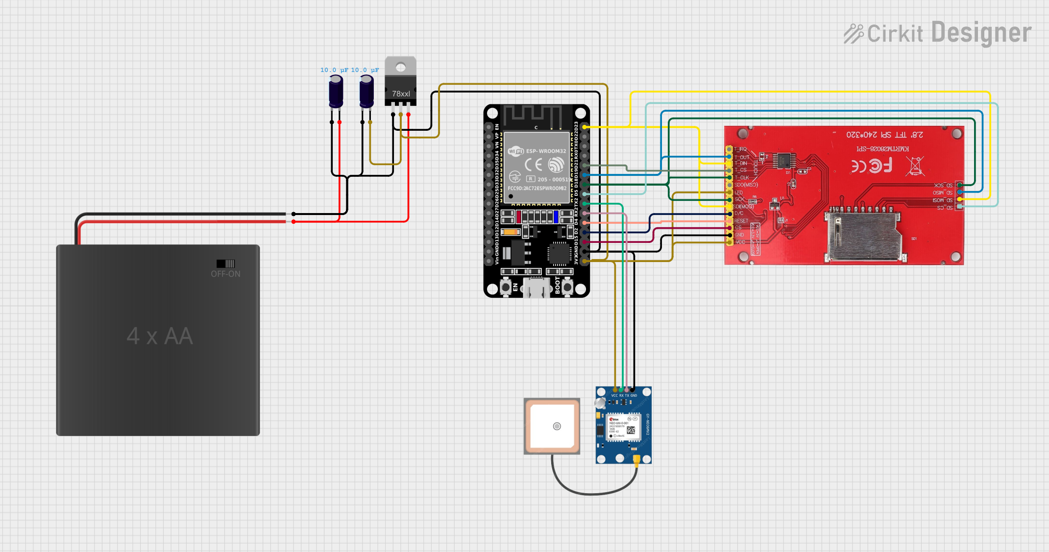
How to Use the ILI9341 in a Circuit
- Power Supply: Connect the
VCCpin to a 3.3V or 5V power source (depending on the module variant) and theGNDpin to ground. - SPI Communication: Connect the
CS,RESET,DC,SDI (MOSI), andSCKpins to the corresponding SPI pins on your microcontroller. - Backlight: Connect the
LEDpin to 3.3V or 5V to enable the backlight. Optionally, use a PWM pin for brightness control. - Touch Functionality: If your module supports touch, connect the
T_IRQpin to an interrupt-capable pin on your microcontroller. - Software Setup: Use a compatible library (e.g., Adafruit_GFX and Adafruit_ILI9341 for Arduino) to initialize and control the display.
Example Arduino UNO Connection
Below is an example of how to connect the ILI9341 module to an Arduino UNO:
| ILI9341 Pin | Arduino UNO Pin |
|---|---|
| VCC | 5V |
| GND | GND |
| CS | Pin 10 |
| RESET | Pin 9 |
| DC | Pin 8 |
| SDI (MOSI) | Pin 11 |
| SCK | Pin 13 |
| LED | 5V |
Example Arduino Code
The following Arduino sketch demonstrates how to initialize and display basic graphics on the ILI9341 module using the Adafruit_ILI9341 library:
#include <Adafruit_GFX.h>      // Core graphics library
#include <Adafruit_ILI9341.h>  // ILI9341 driver library

// Define pin connections
#define TFT_CS   10  // Chip Select
#define TFT_RST  9   // Reset
#define TFT_DC   8   // Data/Command

// Create an instance of the display
Adafruit_ILI9341 tft = Adafruit_ILI9341(TFT_CS, TFT_DC, TFT_RST);

void setup() {
  tft.begin();  // Initialize the display

  // Fill the screen with a solid color
  tft.fillScreen(ILI9341_BLUE);

  // Draw a rectangle
  tft.fillRect(50, 50, 100, 100, ILI9341_RED);

  // Display text
  tft.setTextColor(ILI9341_WHITE);
  tft.setTextSize(2);
  tft.setCursor(10, 10);
  tft.print("Hello, ILI9341!");
}

void loop() {
  // Nothing to do here
}
Important Considerations:
- Ensure the module operates at 3.3V logic levels. Use a level shifter if your microcontroller operates at 5V.
- Avoid connecting the backlight pin (
LED) directly to a GPIO pin without a current-limiting resistor.
Troubleshooting and FAQs
Common Issues and Solutions
Display Not Turning On:
- Verify the power supply connections (
VCCandGND). - Ensure the backlight pin (
LED) is connected to 3.3V or 5V.
- Verify the power supply connections (
No Output or Incorrect Display:
- Check the SPI connections (
CS,RESET,DC,SDI,SCK). - Ensure the correct pins are defined in your code.
- Verify that the Adafruit_ILI9341 library is installed and properly configured.
- Check the SPI connections (
Touch Functionality Not Working:
- Confirm that your module supports touch functionality.
- Check the
T_IRQpin connection and ensure it is configured as an interrupt in your code.
Flickering or Dim Backlight:
- Ensure the backlight pin (
LED) is connected to a stable power source. - If using PWM for brightness control, verify the PWM frequency is appropriate.
- Ensure the backlight pin (
FAQs
Q: Can I use the ILI9341 with a 5V microcontroller?
A: Yes, but you must use level shifters to convert the 5V logic signals to 3.3V to avoid damaging the display.
Q: Does the ILI9341 support parallel communication?
A: The ILI9341 driver IC supports parallel communication, but most 4.0-inch modules are designed for SPI communication.
Q: How do I control the brightness of the backlight?
A: Connect the LED pin to a PWM-capable GPIO pin on your microcontroller and adjust the duty cycle to control brightness.
Q: Can I use this display with platforms other than Arduino?
A: Yes, the ILI9341 is compatible with other platforms like Raspberry Pi, ESP32, and STM32. Ensure you use the appropriate libraries and pin configurations.