How to Use Arduino Fio (Funnel I/O): Examples, Pinouts, and Specs
Introduction
The Arduino Fio (Funnel I/O) is a versatile microcontroller board tailored for wireless projects. It is designed to simplify the process of working with Xbee modules for remote communication. The small form factor of the Arduino Fio makes it an ideal choice for prototyping wearable devices, remote sensors, and other applications where size and wireless capabilities are crucial.
Explore Projects Built with Arduino Fio (Funnel I/O)
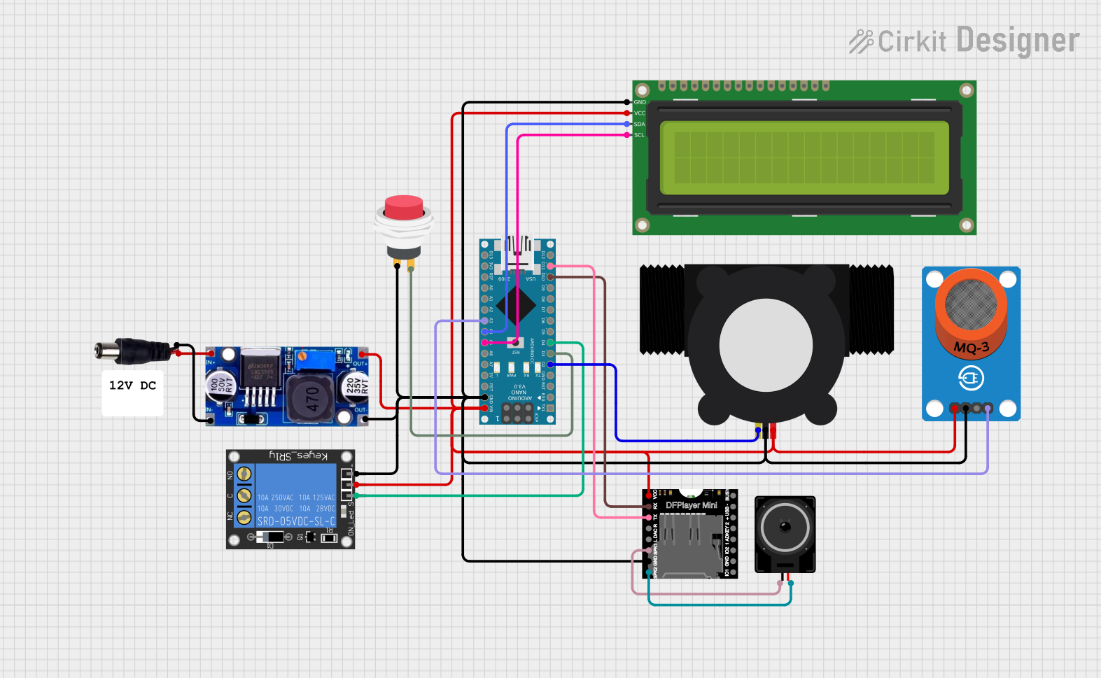
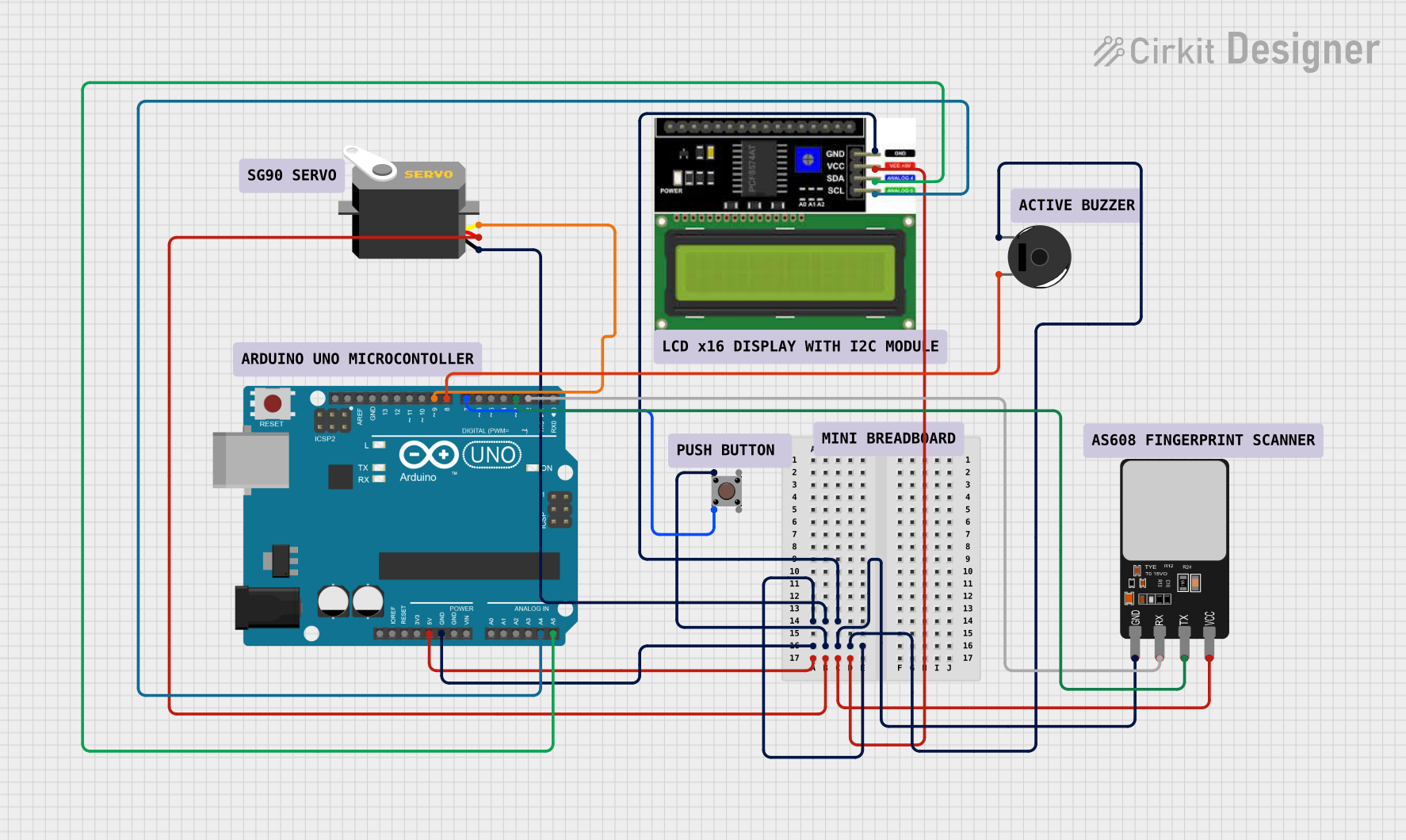
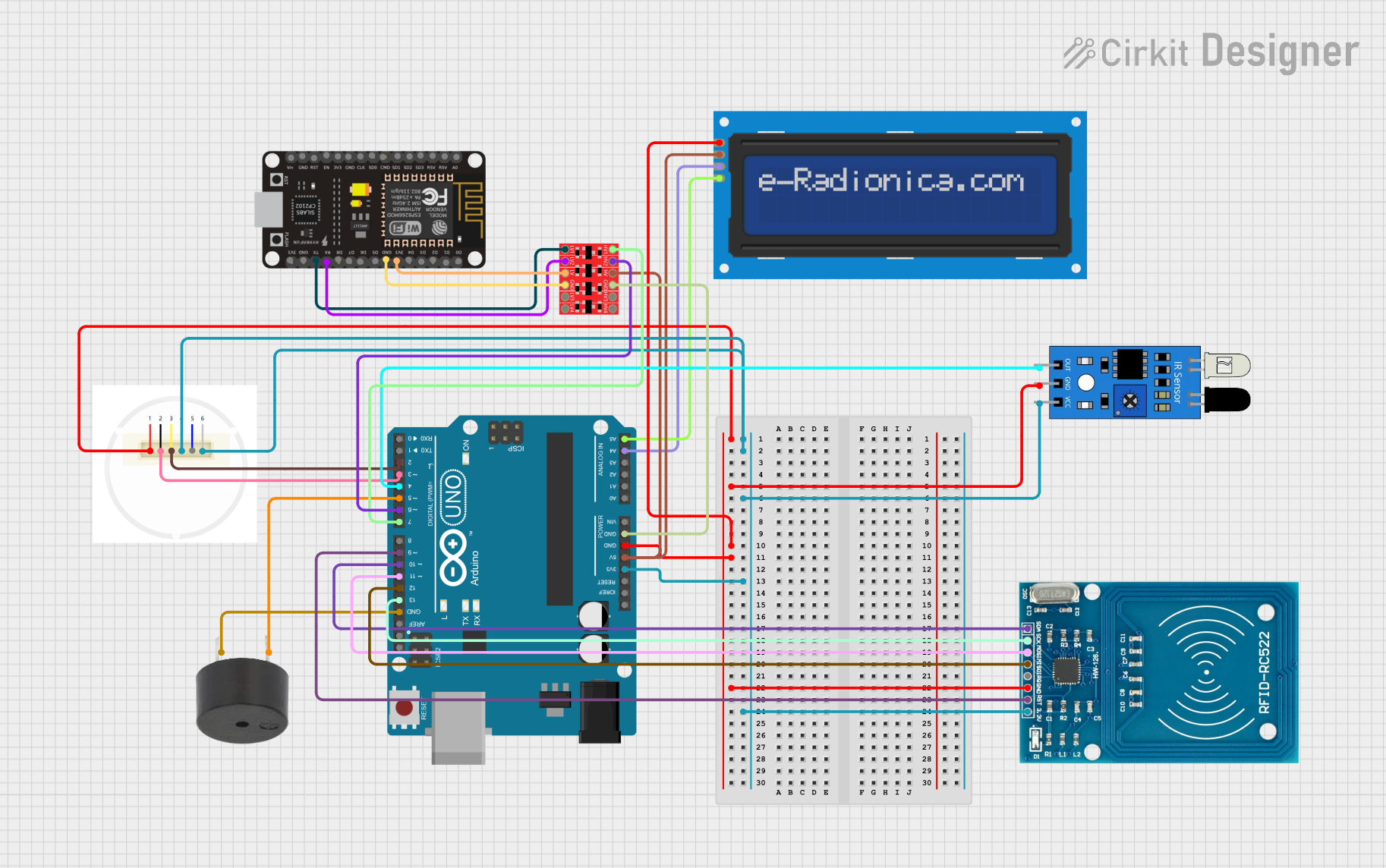

Explore Projects Built with Arduino Fio (Funnel I/O)
Common Applications and Use Cases
- Wearable electronics
- Remote sensor networks
- Wireless data logging
- Home automation systems
- UAVs and robotics
Technical Specifications
Key Technical Details
- Microcontroller: ATmega328P
- Operating Voltage: 3.3V
- Input Voltage: 3.35-12V (battery), 5V (USB)
- Digital I/O Pins: 14 (of which 6 provide PWM output)
- Analog Input Pins: 8
- DC Current per I/O Pin: 40 mA
- Flash Memory: 32 KB (ATmega328P) of which 2 KB used by bootloader
- SRAM: 2 KB (ATmega328P)
- EEPROM: 1 KB (ATmega328P)
- Clock Speed: 8 MHz
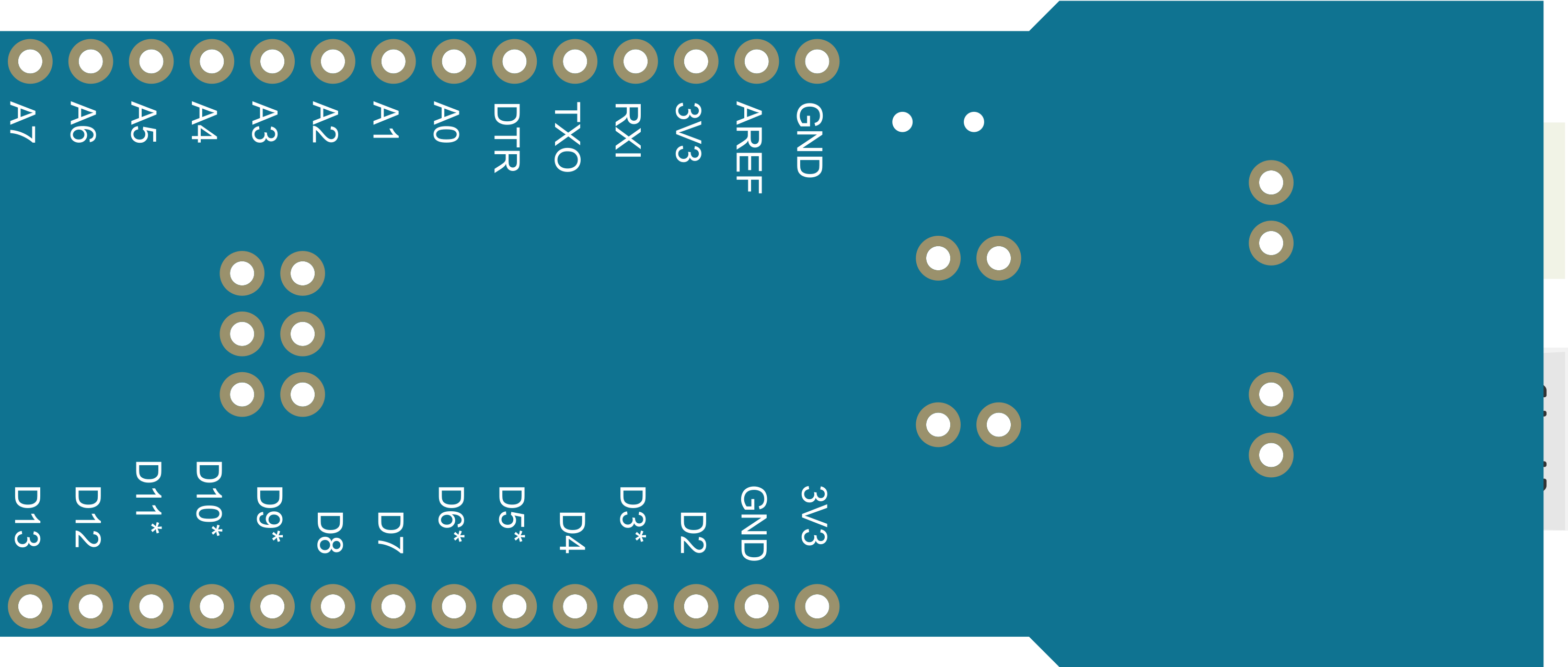
Pin Configuration and Descriptions
| Pin Number | Function | Description |
|---|---|---|
| 1-14 | Digital I/O | Digital pins, PWM available on pins 3, 5, 6, 9, 10, and 11 |
| A0-A7 | Analog Input | Analog input pins |
| AREF | Analog Reference | Reference voltage for the analog inputs |
| GND | Ground | Ground pin |
| RST | Reset | Used to reset the microcontroller |
| 3V3 | 3.3V Supply | 3.3V output from the onboard regulator |
| BAT | Battery Supply | Connection for a LiPo battery |
| TXO | Transmit | UART transmit pin, for serial communication |
| RXI | Receive | UART receive pin, for serial communication |
Usage Instructions
How to Use the Component in a Circuit
Powering the Arduino Fio:
- You can power the Arduino Fio through a LiPo battery connected to the 'BAT' pin or via USB.
Programming the Arduino Fio:
- Connect the board to your computer using a USB cable.
- Select 'Arduino Fio' from the Tools > Board menu in the Arduino IDE.
- Choose the correct serial port from Tools > Port.
- Upload your sketch using the Arduino IDE.
Using the Xbee Socket:
- Insert an Xbee module into the socket, ensuring correct orientation.
- Use the
SoftwareSeriallibrary to communicate with the Xbee module via the digital pins.
Important Considerations and Best Practices
- Always ensure the battery polarity is correct to prevent damage.
- When using the Xbee module, configure it properly for the intended application.
- Avoid exposing the board to moisture or extreme temperatures.
- Disconnect the battery before connecting the board to USB to avoid charging issues.
Troubleshooting and FAQs
Common Issues
- Board not recognized by the computer:
- Ensure the USB cable is properly connected and the correct drivers are installed.
- Xbee module not communicating:
- Check the Xbee configuration and ensure it is compatible with the devices you are trying to communicate with.
- Sketch not uploading:
- Verify the correct board and port are selected in the Arduino IDE. Reset the board and try again.
Solutions and Tips for Troubleshooting
- If the board is not recognized, try a different USB cable or port.
- For Xbee communication issues, use the Xbee configuration software to check the module settings.
- Ensure the battery is charged if the board is not functioning correctly.
FAQs
Q: Can I use the Arduino Fio with a standard Arduino shield? A: The Fio has a different form factor and pinout, so it may not be compatible with standard shields designed for the Arduino Uno or similar boards.
Q: How do I charge the connected LiPo battery? A: The Arduino Fio does not support charging the LiPo battery. You will need an external charger.
Q: What is the maximum range of the Xbee module? A: The range depends on the specific Xbee module used and the environment. Refer to the module's datasheet for detailed information.
Example Code for Arduino UNO
Here is a simple example of how to blink an LED on pin 13 of the Arduino Fio:
// Blink an LED on pin 13

void setup() {
  pinMode(13, OUTPUT); // Initialize pin 13 as an output
}

void loop() {
  digitalWrite(13, HIGH); // Turn the LED on
  delay(1000);            // Wait for a second
  digitalWrite(13, LOW);  // Turn the LED off
  delay(1000);            // Wait for a second
}
Remember to comment your code adequately and keep line lengths within 80 characters for readability.