How to Use RYLR 998 LORA Module : Examples, Pinouts, and Specs
Introduction
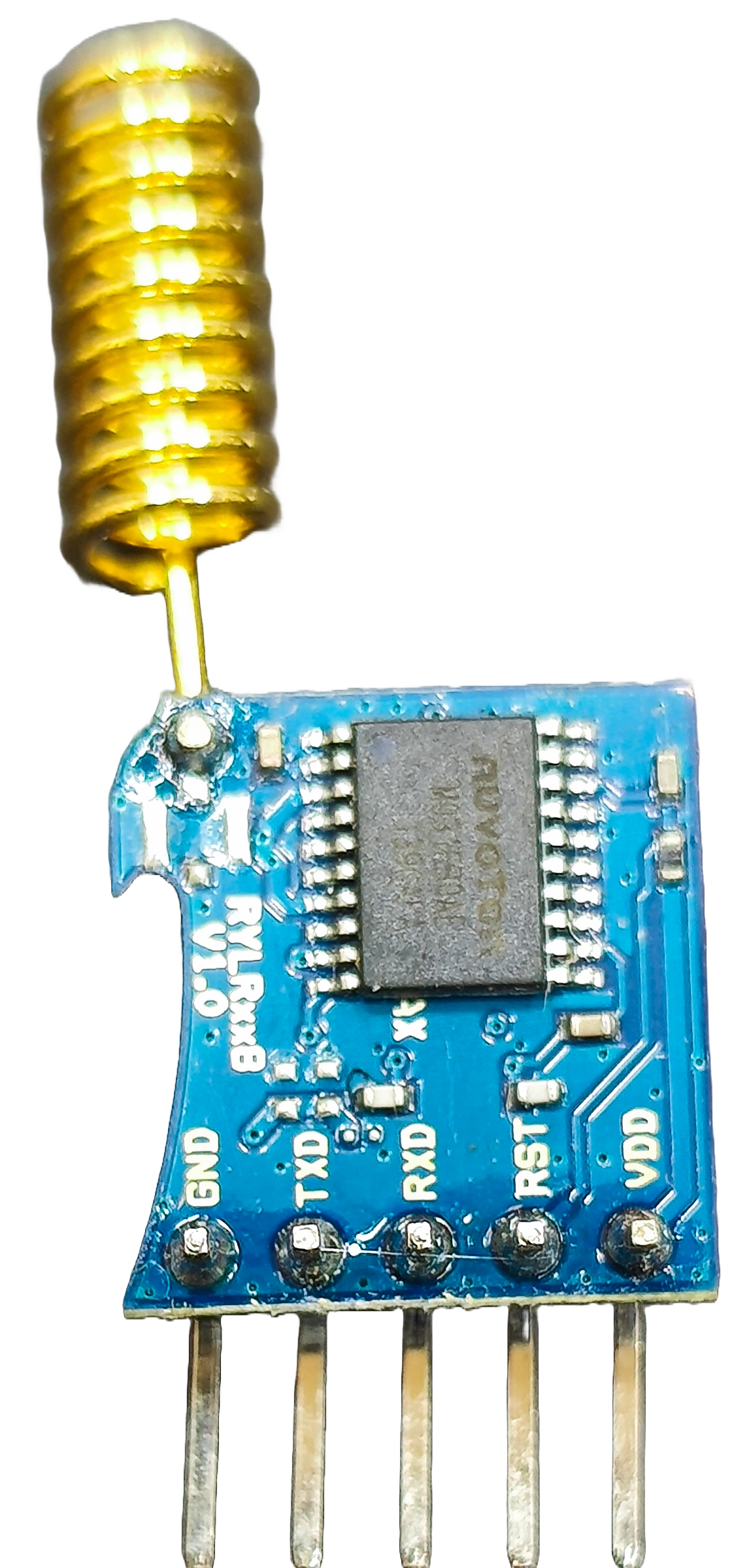
The RYLR 998 LORA Module, manufactured by Rayex, is a low-power, long-range wireless communication module that leverages LoRa (Long Range) technology. This module is specifically designed for IoT (Internet of Things) applications, enabling devices to communicate over distances of several kilometers with minimal power consumption. It supports multiple data rates and is ideal for applications requiring reliable, long-range communication.
Explore Projects Built with RYLR 998 LORA Module


Explore Projects Built with RYLR 998 LORA Module
Common Applications and Use Cases
- Remote Sensing: Environmental monitoring, weather stations, and industrial sensors.
- Smart Agriculture: Crop monitoring, irrigation systems, and livestock tracking.
- Smart Cities: Street lighting control, parking management, and waste management.
- Asset Tracking: Logistics, fleet management, and inventory tracking.
- Home Automation: Wireless control of appliances and security systems.
Technical Specifications
The RYLR 998 LORA Module is designed to provide robust and efficient communication. Below are its key technical details:
Key Technical Details
| Parameter | Specification |
|---|---|
| Frequency Range | 868 MHz / 915 MHz |
| Modulation Technique | LoRa (Long Range) |
| Communication Range | Up to 10 km (line of sight) |
| Data Rate | 0.3 kbps to 37.5 kbps |
| Operating Voltage | 2.8V to 3.6V |
| Operating Current | 15 mA (transmit), 10 µA (sleep mode) |
| Interface | UART (Universal Asynchronous Receiver-Transmitter) |
| Antenna | External antenna (via IPEX connector) |
| Operating Temperature | -40°C to +85°C |
| Dimensions | 18 mm x 25 mm x 3 mm |
Pin Configuration and Descriptions
The RYLR 998 module has a total of 8 pins. Below is the pinout and description:
| Pin Number | Pin Name | Description |
|---|---|---|
| 1 | VCC | Power supply input (2.8V to 3.6V) |
| 2 | GND | Ground connection |
| 3 | TXD | UART Transmit Data |
| 4 | RXD | UART Receive Data |
| 5 | RESET | Module reset (active low) |
| 6 | AUX | Auxiliary pin for status indication |
| 7 | ANT | Antenna connection (via IPEX connector) |
| 8 | NC | Not connected |
Usage Instructions
The RYLR 998 LORA Module is straightforward to integrate into IoT projects. Below are the steps and best practices for using the module:
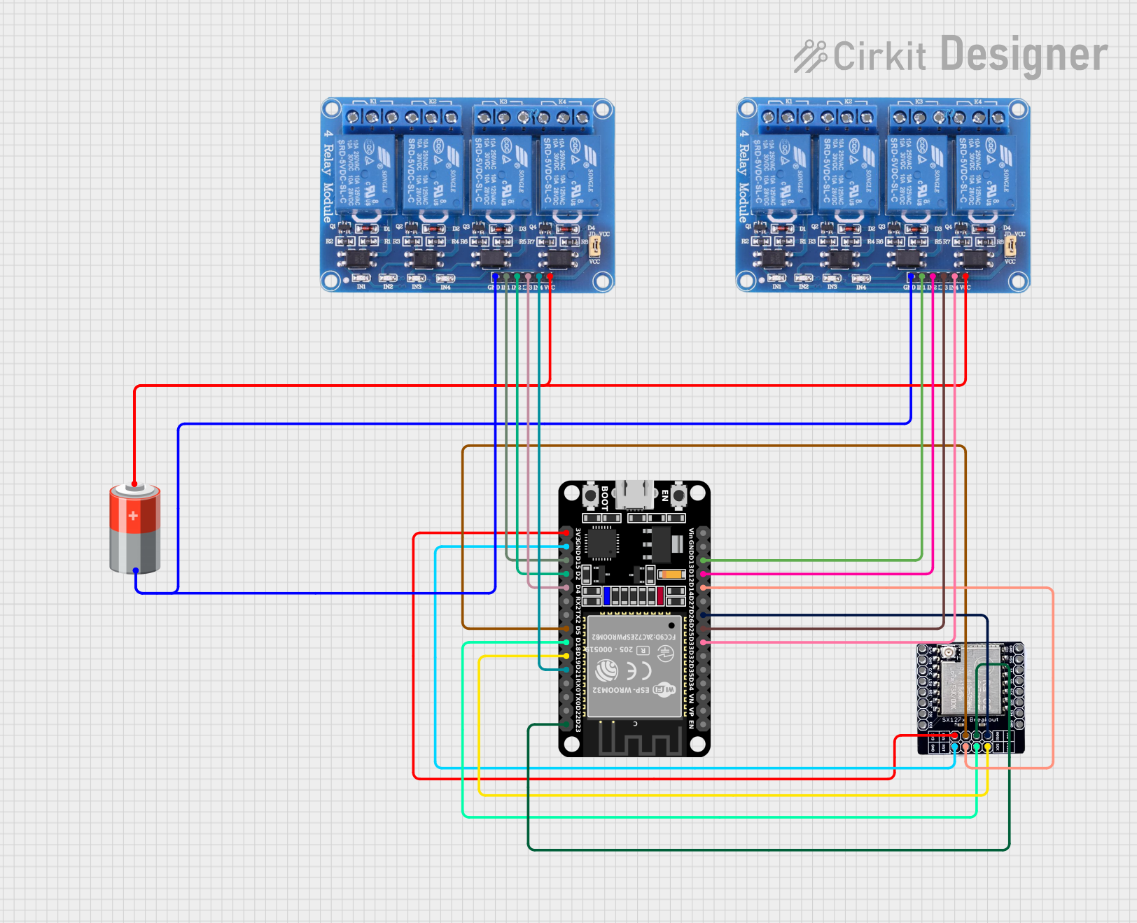
How to Use the Component in a Circuit
- Power Supply: Connect the VCC pin to a 3.3V power source and the GND pin to ground.
- UART Communication: Connect the TXD pin of the module to the RX pin of your microcontroller (e.g., Arduino UNO) and the RXD pin of the module to the TX pin of the microcontroller.
- Antenna: Attach an external antenna to the ANT pin for optimal signal strength.
- Reset: Optionally, connect the RESET pin to a GPIO pin of your microcontroller for manual or software-controlled resets.
Important Considerations and Best Practices
- Power Supply: Ensure a stable 3.3V power supply to avoid communication issues.
- Antenna Placement: Place the antenna in an open area, away from metal objects, to maximize range.
- Baud Rate: The default UART baud rate is 9600 bps. Configure your microcontroller to match this rate.
- Command Set: The module uses AT commands for configuration and communication. Refer to the official AT command set for advanced configurations.
Example: Connecting to an Arduino UNO
Below is an example of how to use the RYLR 998 module with an Arduino UNO:
Circuit Connections
| RYLR 998 Pin | Arduino UNO Pin |
|---|---|
| VCC | 3.3V |
| GND | GND |
| TXD | D2 (Software RX) |
| RXD | D3 (Software TX) |
| RESET | D4 (Optional) |
Arduino Code Example
#include <SoftwareSerial.h>

// Define software serial pins for communication with RYLR 998
SoftwareSerial loraSerial(2, 3); // RX, TX

void setup() {
  // Initialize serial communication with the module
  Serial.begin(9600); // For debugging via Serial Monitor
  loraSerial.begin(9600); // Communication with RYLR 998

  Serial.println("Initializing RYLR 998 Module...");

  // Send an AT command to check module response
  loraSerial.println("AT");
}

void loop() {
  // Check for data from the module
  if (loraSerial.available()) {
    String response = loraSerial.readString();
    Serial.println("Module Response: " + response);
  }

  // Example: Send a message
  if (Serial.available()) {
    String message = Serial.readString();
    loraSerial.println("AT+SEND=0,10," + message);
    // Sends a message to address 0, with length 10
  }
}
Notes:
- Replace
10in theAT+SENDcommand with the actual length of your message. - Ensure the module is properly configured for the desired frequency and data rate using AT commands.
Troubleshooting and FAQs
Common Issues and Solutions
No Response from the Module
- Cause: Incorrect baud rate or wiring.
- Solution: Verify the UART connections and ensure the baud rate is set to 9600 bps.
Limited Communication Range
- Cause: Poor antenna placement or interference.
- Solution: Place the antenna in an open area, away from obstructions and interference sources.
Module Not Powering On
- Cause: Insufficient power supply.
- Solution: Ensure the power supply provides a stable 3.3V and sufficient current.
AT Commands Not Recognized
- Cause: Incorrect command syntax or communication settings.
- Solution: Double-check the AT command syntax and ensure the module is in command mode.
FAQs
Q: Can the RYLR 998 module operate on 5V?
- A: No, the module operates on 2.8V to 3.6V. Use a voltage regulator if your system uses 5V.
Q: What is the maximum data rate supported?
- A: The module supports data rates up to 37.5 kbps.
Q: Can I use the module without an external antenna?
- A: No, an external antenna is required for proper operation and optimal range.
Q: How do I reset the module?
- A: Pull the RESET pin low momentarily to reset the module.
This concludes the documentation for the RYLR 998 LORA Module. For further details, refer to the official datasheet and AT command set provided by Rayex.