How to Use Plug: Examples, Pinouts, and Specs
Introduction
A plug is a device used to connect an electrical appliance to a power source, typically featuring prongs that fit into a socket. It serves as a critical interface between electrical devices and the power supply, ensuring a safe and reliable connection. Plugs are commonly used in households, industries, and commercial settings to power various appliances such as lamps, computers, and kitchen equipment.
Explore Projects Built with Plug

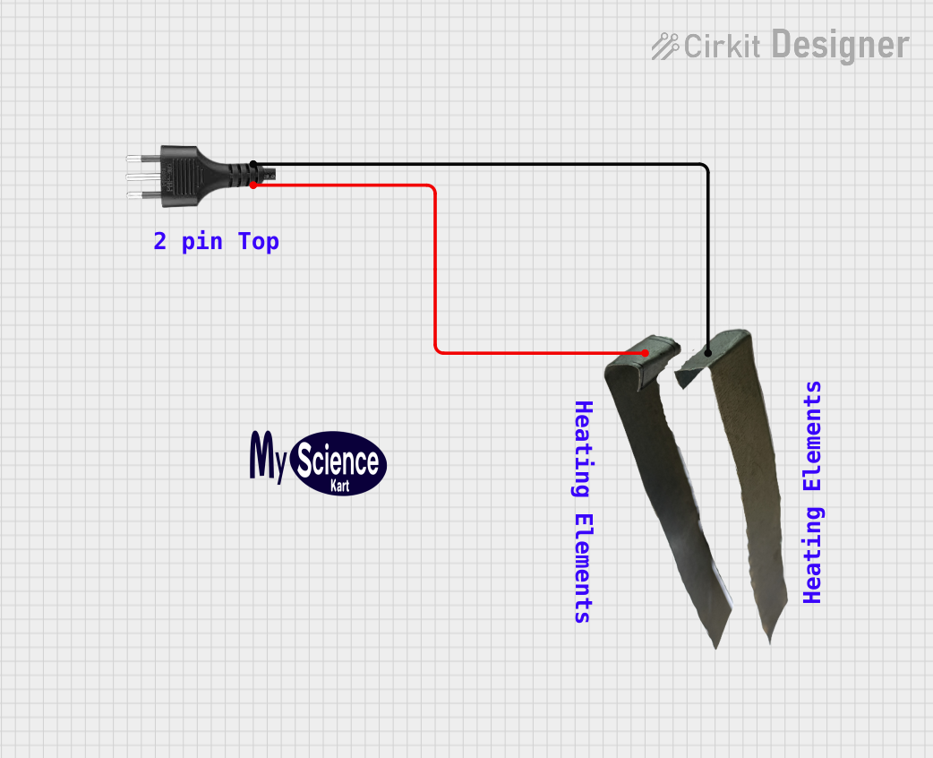


Explore Projects Built with Plug
Common Applications and Use Cases
- Powering household appliances (e.g., refrigerators, televisions, and washing machines)
- Connecting industrial equipment to power sources
- Charging electronic devices like smartphones and laptops
- Temporary power connections for tools and machinery on construction sites
Technical Specifications
Key Technical Details
- Voltage Rating: Typically 110V-240V AC (varies by region)
- Current Rating: Commonly 6A, 10A, or 15A depending on the plug type
- Frequency: 50Hz or 60Hz (region-specific)
- Material: Insulated plastic or rubber housing with metal prongs
- Safety Features: Grounding pin (for three-prong plugs), insulated prongs, and fuse (in some designs)
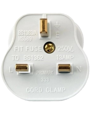
Pin Configuration and Descriptions
Below is a table describing the pin configuration for a standard three-prong plug:
| Pin Name | Description |
|---|---|
| Live (L) | Carries the current from the power source to the appliance. |
| Neutral (N) | Completes the circuit by returning current to the power source. |
| Ground (G) | Provides a safety path for fault currents to prevent electric shock. |
For two-prong plugs, only the Live (L) and Neutral (N) pins are present, and they lack a grounding pin.
Usage Instructions
How to Use the Plug in a Circuit
- Inspect the Plug: Ensure the plug is free from damage, such as frayed wires or bent prongs.
- Connect to the Appliance: Attach the plug to the appliance's power cord securely.
- Insert into the Socket: Align the prongs with the socket and push the plug in firmly.
- Turn on the Power: Switch on the power source to energize the connected appliance.
Important Considerations and Best Practices
- Voltage Compatibility: Verify that the plug's voltage rating matches the power source.
- Grounding: Use a three-prong plug for appliances requiring grounding to ensure safety.
- Avoid Overloading: Do not exceed the plug's current rating to prevent overheating or fire hazards.
- Inspect Regularly: Check for wear and tear, and replace damaged plugs immediately.
- Use Adapters Cautiously: When using plug adapters, ensure they are rated for the appliance's power requirements.
Example: Connecting a Plug to an Arduino UNO Power Supply
If you are using a plug to power an Arduino UNO via an external power adapter, follow these steps:
- Ensure the adapter's output voltage is within the Arduino UNO's input range (7V-12V DC).
- Connect the adapter's plug to a compatible wall socket.
- Insert the adapter's DC barrel jack into the Arduino UNO's power input port.
// Example Arduino code to blink an LED
// This assumes the Arduino UNO is powered via a plug and external adapter

void setup() {
  pinMode(13, OUTPUT); // Set pin 13 as an output for the onboard LED
}

void loop() {
  digitalWrite(13, HIGH); // Turn the LED on
  delay(1000);            // Wait for 1 second
  digitalWrite(13, LOW);  // Turn the LED off
  delay(1000);            // Wait for 1 second
}
Troubleshooting and FAQs
Common Issues Users Might Face
Plug Does Not Fit the Socket:
- Cause: Mismatch between plug and socket type (e.g., Type A plug in a Type C socket).
- Solution: Use a compatible adapter or replace the plug with the correct type.
Appliance Does Not Power On:
- Cause: Loose connection, damaged plug, or faulty socket.
- Solution: Check the plug for damage, ensure it is securely inserted, and test the socket with another device.
Overheating Plug:
- Cause: Overloading or poor contact between the plug and socket.
- Solution: Reduce the load on the plug and ensure the prongs are clean and undamaged.
Sparks When Plugging In:
- Cause: High inrush current or loose socket connections.
- Solution: Plug in firmly and consider using a surge protector for sensitive devices.
Solutions and Tips for Troubleshooting
- Always turn off the power source before inspecting or replacing a plug.
- Use a multimeter to check for continuity and proper voltage at the plug's prongs.
- Replace worn or damaged plugs with new ones that meet the appliance's specifications.
- Consult a licensed electrician for complex issues or if unsure about safety.