How to Use pia horn: Examples, Pinouts, and Specs
Introduction
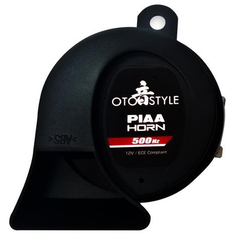
The pia horn is a type of loudspeaker designed to produce a distinctive, high-decibel sound. Its robust construction and ability to generate loud, attention-grabbing tones make it ideal for a variety of applications. Commonly used in alarms, signaling devices, and musical instruments, the pia horn is valued for its reliability and efficiency in sound projection. Its compact size and high output make it a versatile component in both industrial and consumer electronics.
Explore Projects Built with pia horn
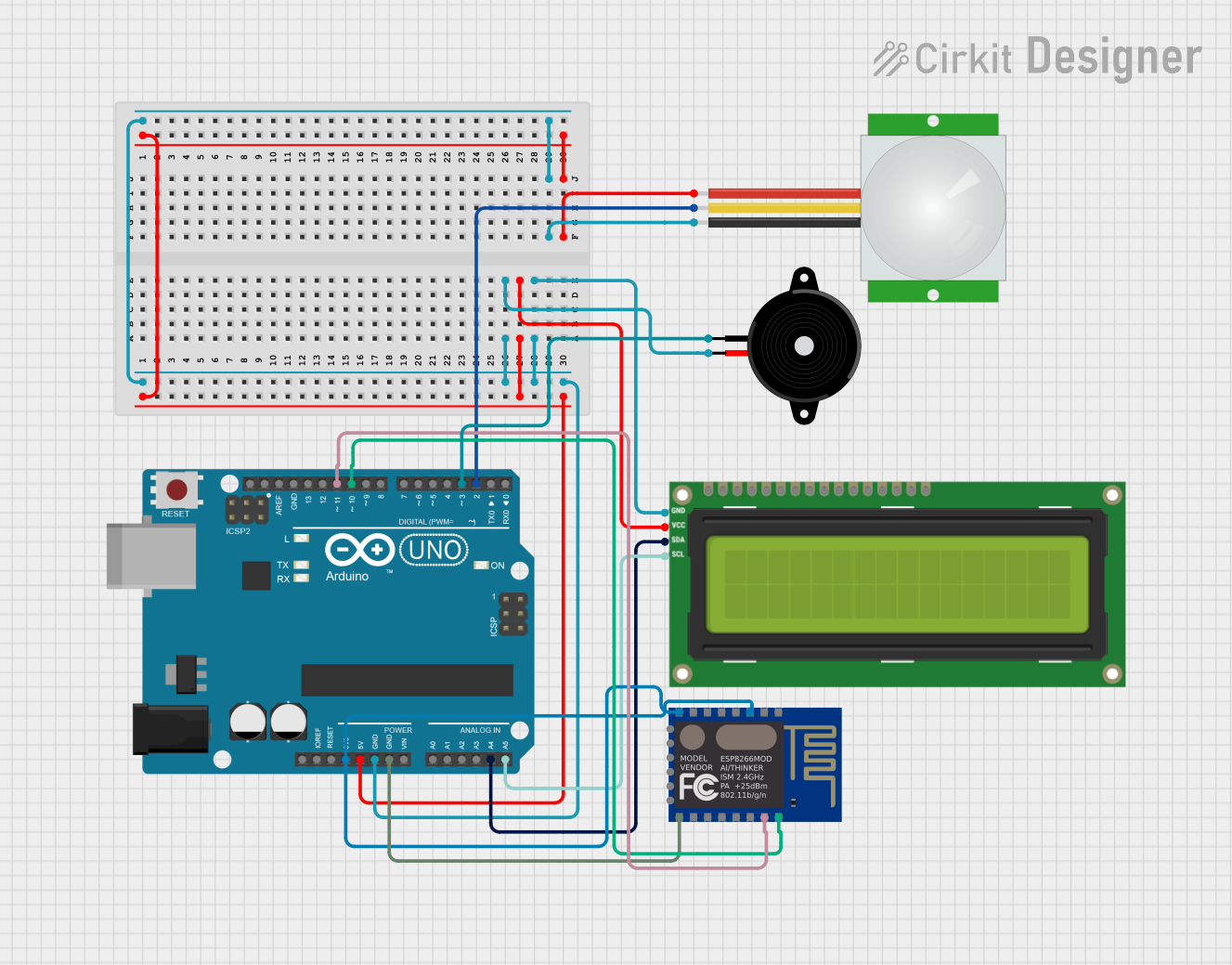
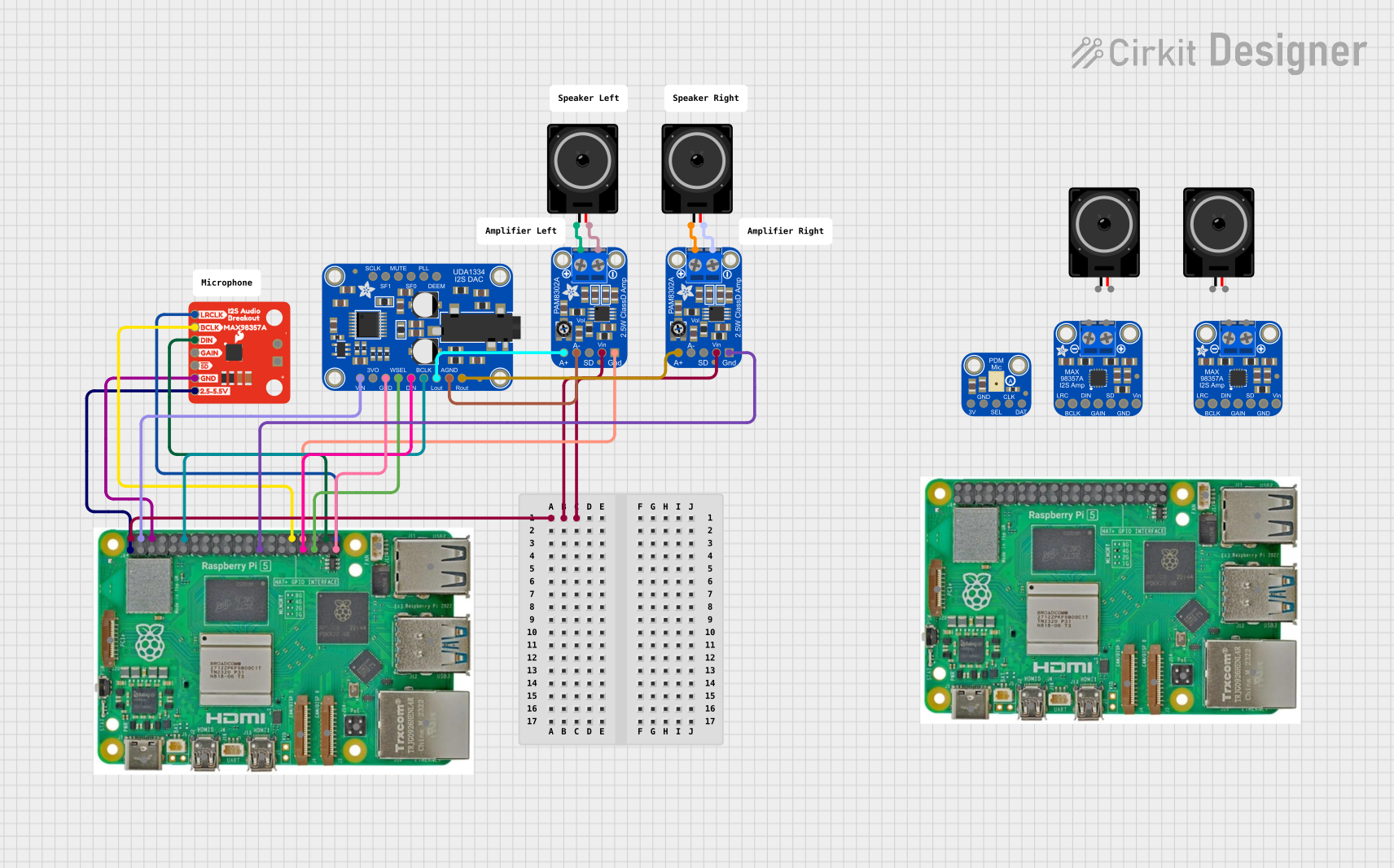
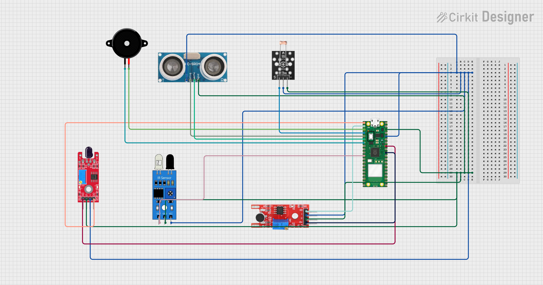
Explore Projects Built with pia horn
Technical Specifications
Below are the key technical details of a typical pia horn:
| Parameter | Value |
|---|---|
| Operating Voltage | 6V to 24V DC |
| Current Consumption | 100mA to 500mA (depending on voltage) |
| Sound Pressure Level | 100dB to 120dB @ 1 meter |
| Frequency Range | 400Hz to 4kHz |
| Impedance | 8Ω to 16Ω |
| Dimensions | Varies (commonly 50mm to 100mm diameter) |
| Material | ABS plastic or metal housing |
Pin Configuration and Descriptions
The pia horn typically has two terminals for connection:
| Pin | Description |
|---|---|
| Positive (+) | Connect to the positive terminal of the power supply or signal source. |
| Negative (-) | Connect to the ground or negative terminal of the power supply. |
Usage Instructions
How to Use the Pia Horn in a Circuit
- Power Supply: Ensure the pia horn is powered within its operating voltage range (6V to 24V DC). Exceeding this range may damage the component.
- Connection: Connect the positive terminal of the pia horn to the positive output of the power supply or signal source. Connect the negative terminal to the ground.
- Signal Input: To produce sound, the pia horn requires an oscillating signal. This can be generated using a microcontroller, such as an Arduino, or a dedicated tone generator circuit.
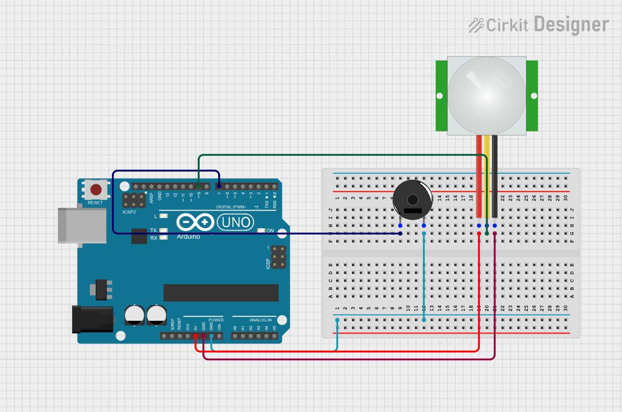
Example: Connecting a Pia Horn to an Arduino UNO
The following example demonstrates how to connect and control a pia horn using an Arduino UNO. The Arduino generates a square wave signal to drive the horn.
Circuit Diagram
- Connect the positive terminal of the pia horn to a digital output pin on the Arduino (e.g., pin 9).
- Connect the negative terminal of the pia horn to the Arduino's GND.
- Use a transistor (e.g., 2N2222) and a resistor (1kΩ) to amplify the signal if the horn requires more current than the Arduino pin can supply.
Arduino Code
// Pia Horn Control Example
// This code generates a square wave to drive the pia horn.
// Ensure the pia horn is connected to pin 9 via a transistor circuit.

const int hornPin = 9; // Pin connected to the pia horn

void setup() {
  pinMode(hornPin, OUTPUT); // Set the horn pin as an output
}

void loop() {
  digitalWrite(hornPin, HIGH); // Turn the horn on
  delay(500);                 // Wait for 500ms
  digitalWrite(hornPin, LOW);  // Turn the horn off
  delay(500);                 // Wait for 500ms
}
Important Considerations and Best Practices
- Current Requirements: If the pia horn requires more current than the microcontroller pin can supply, use a transistor or relay to drive the horn.
- Heat Dissipation: Ensure proper ventilation if the horn is used continuously, as prolonged operation at high decibel levels may generate heat.
- Polarity: Always connect the terminals with the correct polarity to avoid damage.
- Mounting: Secure the pia horn firmly to prevent vibrations or movement during operation.
Troubleshooting and FAQs
Common Issues and Solutions
No Sound from the Horn
- Cause: Incorrect wiring or insufficient power supply.
- Solution: Verify the connections and ensure the power supply meets the voltage and current requirements.
Distorted Sound
- Cause: Signal frequency is outside the horn's operating range or insufficient current.
- Solution: Adjust the signal frequency to fall within the horn's frequency range (400Hz to 4kHz). Use a transistor or relay to provide adequate current.
Overheating
- Cause: Prolonged operation at high decibel levels without proper ventilation.
- Solution: Allow the horn to cool down periodically or improve ventilation around the component.
Intermittent Operation
- Cause: Loose connections or unstable power supply.
- Solution: Check all connections and ensure the power supply is stable.
FAQs
Q: Can I use the pia horn with an AC power supply?
A: No, the pia horn is designed for DC operation only. Using an AC power supply may damage the component.
Q: What is the maximum distance at which the horn can be heard?
A: The audible distance depends on the sound pressure level (SPL) and environmental factors. Typically, a 120dB horn can be heard up to 1 kilometer in open spaces.
Q: Can I use the pia horn for continuous operation?
A: Yes, but ensure proper ventilation and avoid exceeding the recommended voltage and current ratings to prevent overheating.
Q: How do I adjust the tone of the horn?
A: The tone can be adjusted by varying the frequency of the input signal. Use a microcontroller or tone generator to achieve the desired frequency.
This concludes the documentation for the pia horn. Follow the guidelines above to ensure safe and effective operation of this versatile component.