How to Use Ublox NEO-M8N GPS module : Examples, Pinouts, and Specs
Introduction
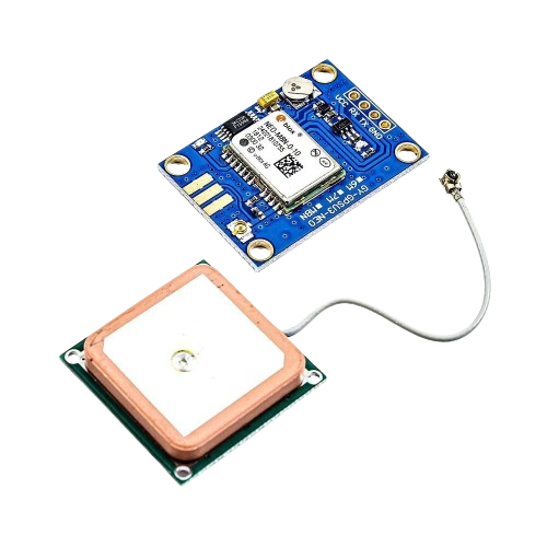
The Ublox NEO-M8N GPS module is a compact, high-performance positioning module featuring the advanced Ublox NEO-M8N chipset. This module is known for its exceptional accuracy, reliability, and power efficiency, making it an ideal solution for a wide range of applications including navigation, tracking systems, drones, and timing synchronization for various devices.
Explore Projects Built with Ublox NEO-M8N GPS module

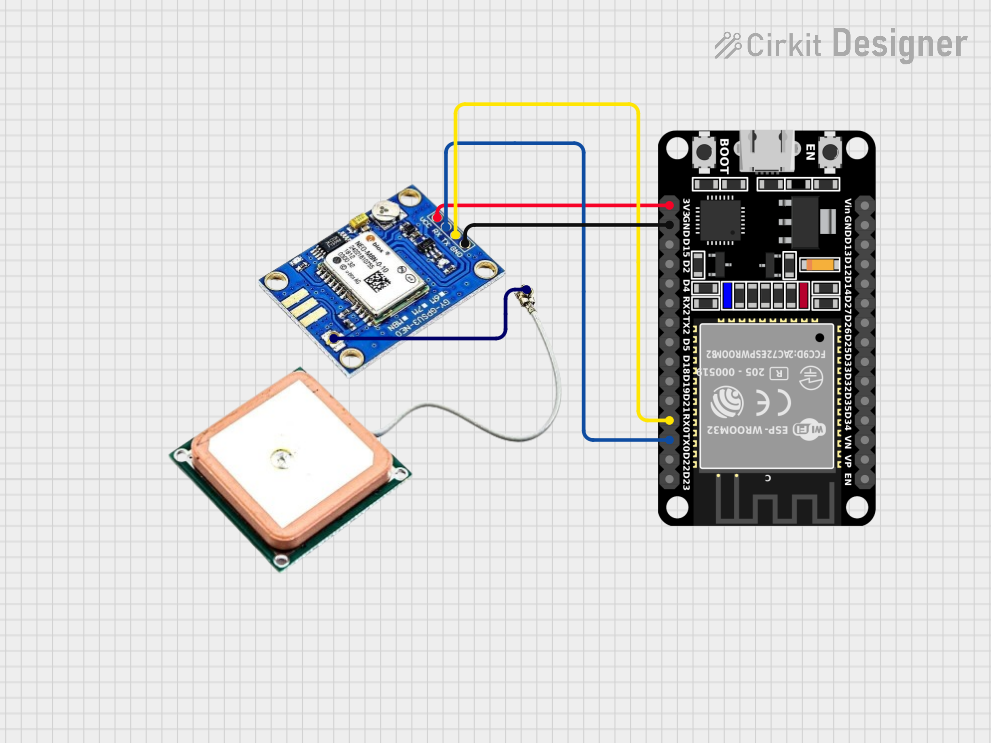
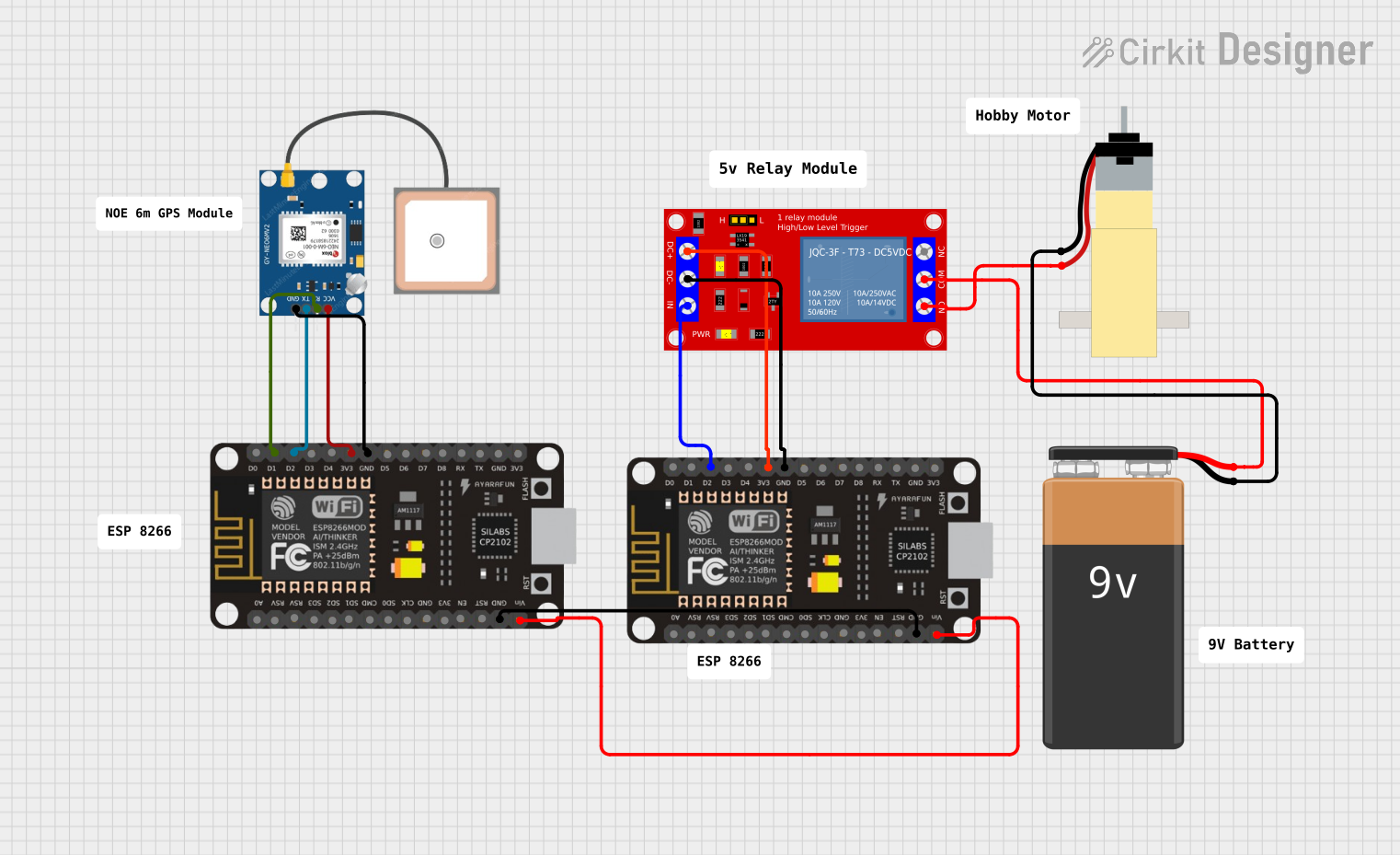
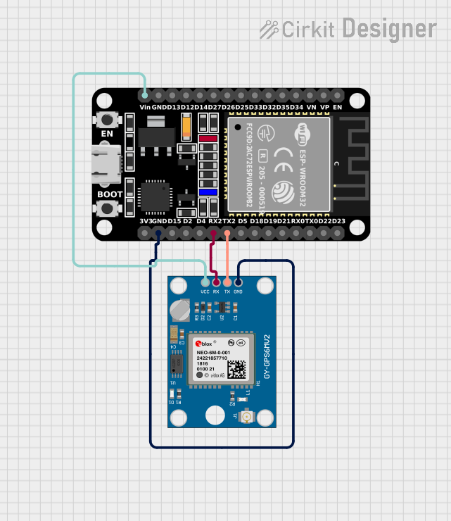
Explore Projects Built with Ublox NEO-M8N GPS module
Common Applications and Use Cases
- Personal and vehicle navigation
- Asset tracking and fleet management
- Unmanned aerial vehicles (UAVs) and drones
- Geotagging and mapping
- Time synchronization for networks
Technical Specifications
Key Technical Details
- Receiver Type: 72-channel u-blox M8 engine
- GPS/QZSS L1 C/A, GLONASS L10F, BeiDou B1
- SBAS: WAAS, EGNOS, MSAS
- Galileo-ready E1B/C (NEO-M8N)
- Nav. Update Rate: Up to 10 Hz
- Position Accuracy: 2 m CEP
- Acquisition Times: Cold starts: 26s, Aided starts: 2s, Reacquisition: 1.5s
- Sensitivity: Tracking & Nav: –167 dBm, Cold starts: –148 dBm
- Oscillator: TCXO (NEO-M8N/Q), Crystal (NEO-M8M)
- RTC crystal: Built-In
- Anti Jamming: Active CW detection and removal. Extra onboard SAW band pass filter (NEO-M8N/Q)
- Power Supply: 1.65 V to 3.6 V
- Power Consumption: 23 mA @ 3.0 V (continuous), 5 mA @ 3.0 V Power Save Mode (1 Hz)
- Operating Temp.: –40° C to 85° C
Pin Configuration and Descriptions
| Pin Number | Name | Description |
|---|---|---|
| 1 | VCC | Power supply (1.65 V to 3.6 V) |
| 2 | GND | Ground |
| 3 | TX | Data output from the module (TXD) |
| 4 | RX | Data input to the module (RXD) |
| 5 | PPS | Pulse Per Second output |
| 6 | SDA | I2C Data |
| 7 | SCL | I2C Clock |
| 8 | RST | Reset input (active low) |
Usage Instructions
How to Use the Component in a Circuit
- Power Supply: Connect the VCC pin to a power source between 1.65 V and 3.6 V and the GND pin to the ground.
- Data Communication: Connect the TX pin of the GPS module to the RX pin of your microcontroller and the RX pin to the TX pin of your microcontroller for serial communication.
- PPS Output: The PPS pin outputs a pulse per second, which can be used for precise timing.
- I2C Communication: If using I2C, connect SDA and SCL to your microcontroller's corresponding I2C pins.
- Reset: The RST pin can be connected to a microcontroller pin for resetting the module programmatically.
Important Considerations and Best Practices
- Ensure that the GPS antenna has a clear view of the sky for optimal performance.
- Avoid placing the module close to sources of electromagnetic interference.
- Use a regulated power supply to prevent damage to the module.
- For initial setup, it may take longer for the module to acquire satellite signals (cold start). Subsequent starts will be faster (hot starts).
Example Arduino UNO Connection and Code
#include <SoftwareSerial.h>

// Connect the GPS module TX to Arduino pin 3 and RX to pin 4
SoftwareSerial gpsSerial(3, 4); // RX, TX

void setup() {
  // Start the serial communication with the host computer
  Serial.begin(9600);
  while (!Serial) {
    ; // Wait for serial port to connect
  }

  // Start the serial communication with the GPS module
  gpsSerial.begin(9600);
}

void loop() {
  // Check if data is available from the GPS module
  if (gpsSerial.available()) {
    // Forward the data from the GPS module to the host computer
    Serial.write(gpsSerial.read());
  }

  // Check if data is available from the host computer
  if (Serial.available()) {
    // Forward the data from the host computer to the GPS module
    gpsSerial.write(Serial.read());
  }
}
Troubleshooting and FAQs
Common Issues Users Might Face
- No GPS Fix: Ensure the antenna has a clear view of the sky and that the module is not near strong electromagnetic fields.
- Garbled Data: Check the baud rate and serial connections. Ensure that the TX/RX connections are not reversed.
- Module Not Powering Up: Verify the power supply voltage and connections.
Solutions and Tips for Troubleshooting
- Cold Start: If the module is taking a long time to get a fix, leave it powered on with a clear view of the sky for several minutes.
- Interference: Use shielded cables for connections and keep the GPS module away from high-power devices.
- Power Issues: Use a multimeter to check the voltage at the VCC pin to ensure it is within the specified range.
FAQs
Q: Can the module be used indoors? A: GPS signals are significantly weakened indoors. It is recommended to use the module outdoors or near a window.
Q: How can I increase the update rate? A: The update rate can be configured using UBX protocol commands. Refer to the u-blox documentation for details.
Q: What is the purpose of the PPS pin? A: The PPS pin provides a pulse per second signal that can be used for precise timing applications.
Q: How do I reset the module? A: The module can be reset by pulling the RST pin low. This can be done manually or programmatically via a microcontroller.
This documentation provides an overview of the Ublox NEO-M8N GPS module, its technical specifications, usage instructions, and troubleshooting tips. For more detailed information, refer to the manufacturer's datasheet and application notes.