How to Use Alphanumeric LED Display: Examples, Pinouts, and Specs
Introduction
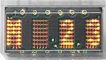
The HCMS-2902 is an alphanumeric LED display module manufactured by Broadcom Limited. It is designed to display alphanumeric characters and symbols using a matrix of light-emitting diodes (LEDs). This compact and versatile display is ideal for applications requiring clear and bright visual output, such as digital clocks, calculators, instrumentation panels, and other electronic devices.
The HCMS-2902 integrates a 5x7 LED dot matrix for each character and includes an onboard CMOS IC for easy interfacing. Its ability to display up to 8 characters in a single module makes it a popular choice for compact designs.
Explore Projects Built with Alphanumeric LED Display


Explore Projects Built with Alphanumeric LED Display
Technical Specifications
Below are the key technical details of the HCMS-2902:
- Manufacturer: Broadcom Limited
- Part Number: HCMS-2902
- Display Type: Alphanumeric LED display
- Number of Characters: 8
- Character Matrix: 5x7 dot matrix
- Operating Voltage: 5V DC
- Current Consumption: 15 mA (typical per character)
- Interface: Serial (CMOS-compatible)
- Brightness: Adjustable via external resistor
- Operating Temperature: -40°C to +85°C
- Dimensions: 20.1mm x 19.6mm x 3.2mm
Pin Configuration and Descriptions
The HCMS-2902 has a 14-pin configuration. The table below describes each pin:
| Pin Number | Pin Name | Description |
|---|---|---|
| 1 | VDD | Positive supply voltage (5V DC). |
| 2 | GND | Ground connection. |
| 3 | DATA IN | Serial data input for character data. |
| 4 | CLK | Clock input for synchronizing data transfer. |
| 5 | ENABLE | Enables the display when set HIGH. |
| 6 | RESET | Resets the display when set LOW. |
| 7 | DATA OUT | Serial data output for cascading multiple units. |
| 8-14 | NC | No connection (reserved for internal use). |
Usage Instructions
How to Use the HCMS-2902 in a Circuit
- Power Supply: Connect the VDD pin to a 5V DC power source and the GND pin to ground.
- Data Input: Use the DATA IN pin to send serial data to the display. The data should be synchronized with the CLK pin.
- Enable Display: Set the ENABLE pin HIGH to activate the display. To turn off the display, set this pin LOW.
- Reset: Use the RESET pin to clear the display. Set it LOW momentarily to reset, then return it to HIGH.
- Cascading: For applications requiring more than 8 characters, connect the DATA OUT pin of one module to the DATA IN pin of the next module.
Important Considerations and Best Practices
- Current Limiting: Use an appropriate resistor to limit the current and prevent damage to the LEDs.
- Data Timing: Ensure proper timing between the DATA IN and CLK signals to avoid data corruption.
- Brightness Control: Adjust the brightness by modifying the external resistor value as specified in the datasheet.
- Cascading Modules: When cascading multiple modules, ensure the CLK and ENABLE signals are shared across all modules.
Example: Connecting to an Arduino UNO
Below is an example of how to connect and program the HCMS-2902 with an Arduino UNO:
Circuit Connections
- Connect the VDD pin to the Arduino's 5V pin.
- Connect the GND pin to the Arduino's GND pin.
- Connect the DATA IN pin to Arduino digital pin 2.
- Connect the CLK pin to Arduino digital pin 3.
- Connect the ENABLE pin to Arduino digital pin 4.
- Connect the RESET pin to Arduino digital pin 5.
Arduino Code
// Define pin connections for the HCMS-2902
#define DATA_IN 2   // Serial data input
#define CLK 3       // Clock input
#define ENABLE 4    // Enable display
#define RESET 5     // Reset display

void setup() {
  // Set pin modes
  pinMode(DATA_IN, OUTPUT);
  pinMode(CLK, OUTPUT);
  pinMode(ENABLE, OUTPUT);
  pinMode(RESET, OUTPUT);

  // Initialize the display
  digitalWrite(RESET, LOW);  // Reset the display
  delay(10);                 // Wait for 10ms
  digitalWrite(RESET, HIGH); // End reset
  digitalWrite(ENABLE, HIGH); // Enable the display
}

void loop() {
  // Example: Send a character to the display
  sendCharacter('A');  // Display the letter 'A'
  delay(1000);         // Wait for 1 second
}

// Function to send a character to the HCMS-2902
void sendCharacter(char character) {
  for (int i = 0; i < 8; i++) {
    // Send each bit of the character data
    digitalWrite(DATA_IN, (character >> i) & 0x01);
    digitalWrite(CLK, HIGH);  // Pulse the clock
    delayMicroseconds(10);    // Short delay
    digitalWrite(CLK, LOW);   // End clock pulse
  }
}
Troubleshooting and FAQs
Common Issues and Solutions
Display Not Turning On:
- Ensure the VDD and GND pins are properly connected.
- Verify that the ENABLE pin is set HIGH.
Characters Not Displaying Correctly:
- Check the timing of the DATA IN and CLK signals.
- Ensure the correct character data is being sent.
Brightness Too Low:
- Verify the external resistor value for brightness control.
- Ensure the power supply provides sufficient current.
Cascaded Modules Not Working:
- Confirm that the DATA OUT pin of the first module is connected to the DATA IN pin of the next module.
- Ensure CLK and ENABLE signals are shared across all modules.
FAQs
Q: Can I use the HCMS-2902 with a 3.3V microcontroller?
A: The HCMS-2902 is designed for 5V operation. Use a level shifter to interface with 3.3V systems.
Q: How many modules can I cascade together?
A: The number of modules you can cascade depends on the driving capability of your microcontroller and the power supply. Typically, up to 4 modules can be cascaded without additional drivers.
Q: Can I display custom symbols?
A: Yes, you can create custom symbols by sending the appropriate 5x7 dot matrix data to the display.
This concludes the documentation for the HCMS-2902 alphanumeric LED display. For further details, refer to the manufacturer's datasheet.