
How to Use Analog Signal Isolator PCB Module for Arduino ESP32 STM32 - 5V ISO: Examples, Pinouts, and Specs
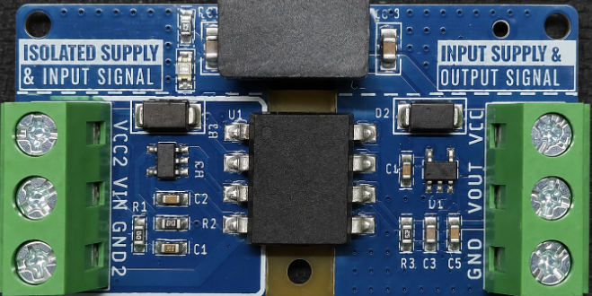
 Design with Analog Signal Isolator PCB Module for Arduino ESP32 STM32 - 5V ISO in Cirkit Designer
Introduction
The Analog Signal Isolator PCB Module is a versatile and reliable component designed to isolate analog signals in microcontroller-based applications. Manufactured by Arduino, this module is compatible with popular platforms such as Arduino, ESP32, and STM32. Operating at 5V, it ensures signal integrity by preventing ground loops and protecting sensitive components from voltage spikes or electrical noise.
This module is particularly useful in scenarios where analog signals need to be transmitted between circuits with different ground potentials or where electrical isolation is critical for safety and performance.
Explore Projects Built with Analog Signal Isolator PCB Module for Arduino ESP32 STM32 - 5V ISO
 Open Project in Cirkit Designer
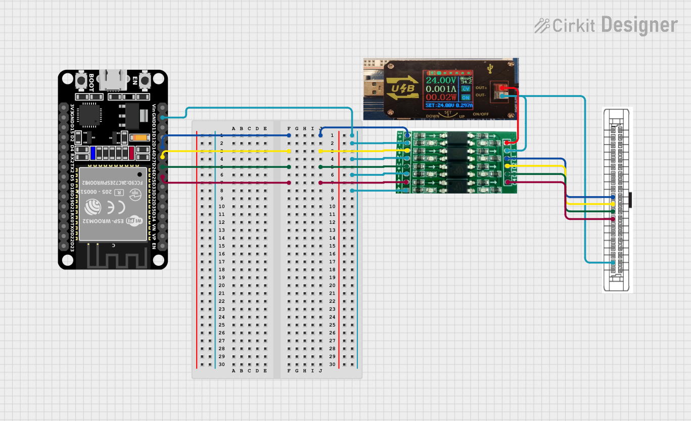 Open Project in Cirkit Designer
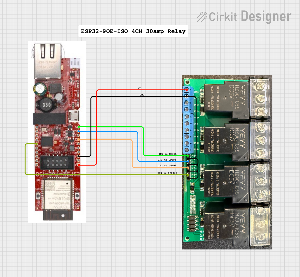 Open Project in Cirkit Designer
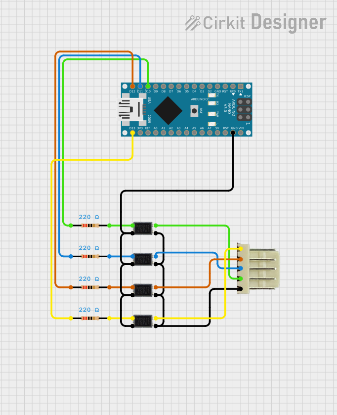 Open Project in Cirkit Designer
Explore Projects Built with Analog Signal Isolator PCB Module for Arduino ESP32 STM32 - 5V ISO
Open Project in Cirkit DesignerOpen Project in Cirkit DesignerOpen Project in Cirkit DesignerOpen Project in Cirkit DesignerCommon Applications
- Industrial automation and control systems
- Signal conditioning in sensor-based applications
- Noise suppression in analog signal transmission
- Protection of microcontroller inputs from high-voltage spikes
- Medical instrumentation and measurement systems
Technical Specifications
Key Technical Details
| Parameter | Value |
|---|---|
| Manufacturer | Arduino |
| Manufacturer Part ID | Analog Signal Isolator |
| Operating Voltage | 5V DC |
| Signal Input Range | 0-5V |
| Signal Output Range | 0-5V |
| Isolation Voltage | 2500V AC |
| Operating Temperature | -40°C to +85°C |
| Dimensions | 25mm x 20mm x 10mm |
| Compatible Platforms | Arduino, ESP32, STM32 |
Pin Configuration and Descriptions
| Pin Name | Pin Number | Description |
|---|---|---|
| VCC | 1 | Power supply input (5V DC) |
| GND | 2 | Ground connection |
| IN | 3 | Analog signal input (0-5V) |
| OUT | 4 | Isolated analog signal output (0-5V) |
Usage Instructions
How to Use the Component in a Circuit
- Power the Module: Connect the
VCCpin to a 5V DC power source and theGNDpin to the ground of the power supply. - Input Signal: Feed the analog signal (0-5V) to the
INpin. Ensure the input signal does not exceed the specified range to avoid damage. - Output Signal: The isolated analog signal will be available at the
OUTpin. Connect this pin to the desired microcontroller or circuit input. - Ground Isolation: Ensure that the ground of the input circuit is not directly connected to the ground of the output circuit to maintain isolation.
Important Considerations and Best Practices
- Signal Range: Ensure the input signal remains within the 0-5V range. Use a voltage divider or signal conditioning circuit if the input exceeds this range.
- Power Supply: Use a stable 5V DC power supply to avoid fluctuations in the output signal.
- Isolation: Do not connect the input and output grounds directly, as this will defeat the purpose of isolation.
- Mounting: Secure the module on a PCB or breadboard to prevent accidental disconnections or short circuits.
Example Code for Arduino UNO
Below is an example of how to read the isolated analog signal using an Arduino UNO:
// Example code to read an isolated analog signal using Arduino UNO

const int analogInputPin = A0; // Pin A0 is connected to the OUT pin of the module

void setup() {
  Serial.begin(9600); // Initialize serial communication at 9600 baud
  pinMode(analogInputPin, INPUT); // Set the analog input pin as input
}

void loop() {
  int analogValue = analogRead(analogInputPin);
  // Read the analog value from the OUT pin of the isolator module

  float voltage = (analogValue / 1023.0) * 5.0;
  // Convert the analog value to voltage (0-5V range)

  Serial.print("Analog Value: ");
  Serial.print(analogValue); // Print the raw analog value
  Serial.print(" | Voltage: ");
  Serial.print(voltage); // Print the converted voltage
  Serial.println(" V");

  delay(500); // Wait for 500ms before the next reading
}
Troubleshooting and FAQs
Common Issues and Solutions
| Issue | Possible Cause | Solution |
|---|---|---|
| No output signal | Incorrect wiring | Verify all connections and pin mappings. |
| Output signal is noisy or unstable | Power supply fluctuations | Use a regulated 5V DC power supply. |
| Ground loop issues | Input and output grounds are connected | Ensure proper isolation of grounds. |
| Signal distortion | Input signal exceeds 0-5V range | Use a voltage divider or conditioning circuit. |
FAQs
Q1: Can this module handle signals above 5V?
A1: No, the module is designed for a 0-5V signal range. Use a voltage divider or signal conditioning circuit for higher voltages.
Q2: Is this module compatible with 3.3V systems?
A2: The module operates at 5V, but the output can be interfaced with 3.3V systems using a level shifter or resistor divider.
Q3: How does this module protect against ground loops?
A3: The module electrically isolates the input and output circuits, preventing direct ground connections and eliminating ground loop issues.
Q4: Can I use this module for digital signals?
A4: This module is optimized for analog signals. For digital signal isolation, consider using an optocoupler or digital isolator module.
This concludes the documentation for the Analog Signal Isolator PCB Module for Arduino ESP32 STM32 - 5V ISO. For further assistance, refer to the manufacturer's datasheet or contact Arduino support.