Cirkit Designer Logo
Cirkit Designer
Your all-in-one circuit design IDE
Home / 
Component Documentation

How to Use LILYGO T-Beam Meshtastic LORA32 915MHz: Examples, Pinouts, and Specs

Image of LILYGO T-Beam Meshtastic LORA32 915MHz
Cirkit Designer LogoDesign with LILYGO T-Beam Meshtastic LORA32 915MHz in Cirkit Designer

Introduction

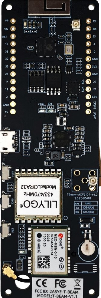
The LILYGO T-Beam Meshtastic LORA32 915MHz is a compact development board designed for long-range wireless communication and mesh networking applications. It features a LoRa transceiver operating at 915MHz, integrated GPS functionality, and is powered by the CH9102 USB-to-serial chip for reliable communication with host devices. This board is ideal for IoT projects, remote sensing, and peer-to-peer communication in areas with limited or no cellular coverage.

Explore Projects Built with LILYGO T-Beam Meshtastic LORA32 915MHz

Use Cirkit Designer to design, explore, and prototype these projects online. Some projects support real-time simulation. Click "Open Project" to start designing instantly!
Dual-Mode LoRa and GSM Communication Device with ESP32
Image of modul gateway: A project utilizing LILYGO T-Beam Meshtastic LORA32 915MHz in a practical application
This circuit features an ESP32 Devkit V1 microcontroller interfaced with an RFM95 LoRa transceiver module for long-range communication and a SIM800L GSM module for cellular connectivity. Two LM2596 step-down modules are used to regulate the 12V battery voltage down to 3.3V required by the ESP32, RFM95, and SIM800L. The ESP32 facilitates data exchange between the RFM95 and SIM800L, enabling the system to send/receive data over both LoRa and GSM networks.
Cirkit Designer LogoOpen Project in Cirkit Designer
ESP32 and RFM95 LoRa Transmitter with Inductor-Based Antenna
Image of transmitter LoRa: A project utilizing LILYGO T-Beam Meshtastic LORA32 915MHz in a practical application
This circuit is a LoRa transmitter system that uses an ESP32 microcontroller to communicate with an RFM95 LoRa module. The ESP32 initializes the LoRa module and sends periodic messages wirelessly, with an inductor connected to the antenna pin of the RFM95 for signal tuning.
Cirkit Designer LogoOpen Project in Cirkit Designer
Cellular-Enabled IoT Device with Real-Time Clock and Power Management
Image of LRCM PHASE 2 BASIC: A project utilizing LILYGO T-Beam Meshtastic LORA32 915MHz in a practical application
This circuit features a LilyGo-SIM7000G module for cellular communication and GPS functionality, interfaced with an RTC DS3231 for real-time clock capabilities. It includes voltage sensing through two voltage sensor modules, and uses an 8-channel opto-coupler for isolating different parts of the circuit. Power management is handled by a buck converter connected to a DC power source and batteries, with a fuse for protection and a rocker switch for on/off control. Additionally, there's an LED for indication purposes.
Cirkit Designer LogoOpen Project in Cirkit Designer
Arduino Nano-Based GPS Tracker with GSM and LoRa Communication
Image of Electromagnetic Sensor: A project utilizing LILYGO T-Beam Meshtastic LORA32 915MHz in a practical application
This circuit features an Arduino Nano microcontroller interfaced with an RFM95 LoRa transceiver module for long-range communication, a SIM800L GSM module for cellular connectivity, and a GPS NEO 6M module for location tracking. The Arduino Nano also connects to an inductive sensor for proximity or metal detection. The circuit is designed for applications requiring wireless communication, location tracking, and proximity sensing, with the Arduino Nano serving as the central processing unit.
Cirkit Designer LogoOpen Project in Cirkit Designer

Explore Projects Built with LILYGO T-Beam Meshtastic LORA32 915MHz

Use Cirkit Designer to design, explore, and prototype these projects online. Some projects support real-time simulation. Click "Open Project" to start designing instantly!
Image of modul gateway: A project utilizing LILYGO T-Beam Meshtastic LORA32 915MHz in a practical application
Dual-Mode LoRa and GSM Communication Device with ESP32
This circuit features an ESP32 Devkit V1 microcontroller interfaced with an RFM95 LoRa transceiver module for long-range communication and a SIM800L GSM module for cellular connectivity. Two LM2596 step-down modules are used to regulate the 12V battery voltage down to 3.3V required by the ESP32, RFM95, and SIM800L. The ESP32 facilitates data exchange between the RFM95 and SIM800L, enabling the system to send/receive data over both LoRa and GSM networks.
Cirkit Designer LogoOpen Project in Cirkit Designer
Image of transmitter LoRa: A project utilizing LILYGO T-Beam Meshtastic LORA32 915MHz in a practical application
ESP32 and RFM95 LoRa Transmitter with Inductor-Based Antenna
This circuit is a LoRa transmitter system that uses an ESP32 microcontroller to communicate with an RFM95 LoRa module. The ESP32 initializes the LoRa module and sends periodic messages wirelessly, with an inductor connected to the antenna pin of the RFM95 for signal tuning.
Cirkit Designer LogoOpen Project in Cirkit Designer
Image of LRCM PHASE 2 BASIC: A project utilizing LILYGO T-Beam Meshtastic LORA32 915MHz in a practical application
Cellular-Enabled IoT Device with Real-Time Clock and Power Management
This circuit features a LilyGo-SIM7000G module for cellular communication and GPS functionality, interfaced with an RTC DS3231 for real-time clock capabilities. It includes voltage sensing through two voltage sensor modules, and uses an 8-channel opto-coupler for isolating different parts of the circuit. Power management is handled by a buck converter connected to a DC power source and batteries, with a fuse for protection and a rocker switch for on/off control. Additionally, there's an LED for indication purposes.
Cirkit Designer LogoOpen Project in Cirkit Designer
Image of Electromagnetic Sensor: A project utilizing LILYGO T-Beam Meshtastic LORA32 915MHz in a practical application
Arduino Nano-Based GPS Tracker with GSM and LoRa Communication
This circuit features an Arduino Nano microcontroller interfaced with an RFM95 LoRa transceiver module for long-range communication, a SIM800L GSM module for cellular connectivity, and a GPS NEO 6M module for location tracking. The Arduino Nano also connects to an inductive sensor for proximity or metal detection. The circuit is designed for applications requiring wireless communication, location tracking, and proximity sensing, with the Arduino Nano serving as the central processing unit.
Cirkit Designer LogoOpen Project in Cirkit Designer

Common Applications and Use Cases

  • Mesh networking for communication in remote areas
  • IoT applications requiring long-range wireless connectivity
  • GPS-based tracking and navigation systems
  • Disaster recovery communication networks
  • Environmental monitoring and data collection

Technical Specifications

Key Technical Details

Parameter Specification
Manufacturer LILYGO
Part ID CH9102
LoRa Frequency 915MHz
GPS Module Integrated GPS functionality
USB-to-Serial Chip CH9102
Power Supply 5V via USB or 3.7V LiPo battery
Communication Protocol LoRaWAN, Meshtastic
Dimensions 30mm x 70mm
Operating Temperature -40°C to 85°C

Pin Configuration and Descriptions

Pin Name Description
3V3 3.3V power output
GND Ground
TXD UART Transmit Data
RXD UART Receive Data
GPIO0 General Purpose Input/Output 0
GPIO1 General Purpose Input/Output 1
GPS_TX GPS Transmit Data
GPS_RX GPS Receive Data
BAT LiPo battery input
EN Enable pin for power management

Usage Instructions

How to Use the Component in a Circuit

  1. Powering the Board:

    • Connect the board to a 5V USB power source or use a 3.7V LiPo battery via the BAT pin.
    • Ensure the power source provides sufficient current for both the LoRa transceiver and GPS module.
  2. Connecting to a Host Device:

    • Use a USB cable to connect the T-Beam to your computer. The CH9102 chip will handle USB-to-serial communication.
    • Install the necessary CH9102 drivers on your computer if not already available.
  3. Programming the Board:

    • The T-Beam is compatible with the Arduino IDE. Install the ESP32 board package in the Arduino IDE.
    • Select the correct board (ESP32 Dev Module) and port in the Arduino IDE.
  4. Using LoRa Communication:

    • Connect an appropriate antenna to the LoRa module for optimal performance.
    • Use the Meshtastic firmware or write custom code to enable LoRa communication.
  5. GPS Functionality:

    • Ensure the GPS antenna is connected and has a clear view of the sky for accurate positioning.
    • Use the GPS_TX and GPS_RX pins to interface with the GPS module if needed.

Important Considerations and Best Practices

  • Always connect an antenna to the LoRa module before powering the board to avoid damage.
  • Use a stable power source to ensure reliable operation of the LoRa and GPS modules.
  • When using a LiPo battery, monitor the battery voltage to prevent over-discharge.
  • For outdoor applications, consider using a weatherproof enclosure to protect the board.

Example Code for Arduino UNO

Below is an example of how to send a simple message using the LoRa module on the T-Beam:

#include <SPI.h>
#include <LoRa.h>

// Define LoRa parameters
#define LORA_SS 18    // LoRa chip select pin
#define LORA_RST 14   // LoRa reset pin
#define LORA_DIO0 26  // LoRa DIO0 pin

void setup() {
  Serial.begin(9600); // Initialize serial communication
  while (!Serial);

  Serial.println("Initializing LoRa...");

  // Initialize LoRa module
  LoRa.setPins(LORA_SS, LORA_RST, LORA_DIO0);
  if (!LoRa.begin(915E6)) { // Set frequency to 915 MHz
    Serial.println("LoRa initialization failed!");
    while (1);
  }

  Serial.println("LoRa initialized successfully.");
}

void loop() {
  Serial.println("Sending message...");
  LoRa.beginPacket();               // Start a new LoRa packet
  LoRa.print("Hello, LoRa World!"); // Add message to the packet
  LoRa.endPacket();                 // Send the packet

  delay(5000); // Wait 5 seconds before sending the next message
}

Troubleshooting and FAQs

Common Issues and Solutions

  1. LoRa Module Not Initializing:

    • Ensure the antenna is properly connected to the LoRa module.
    • Verify that the correct frequency (915MHz) is set in the code.
    • Check the wiring of the LoRa pins (SS, RST, DIO0) to ensure proper connections.
  2. GPS Not Acquiring Signal:

    • Make sure the GPS antenna has a clear view of the sky.
    • Allow sufficient time for the GPS module to acquire satellite signals.
    • Verify the GPS_TX and GPS_RX pin connections if using them directly.
  3. Board Not Detected by Computer:

    • Install the CH9102 USB-to-serial driver on your computer.
    • Try a different USB cable or port to rule out hardware issues.
  4. Power Issues:

    • Ensure the power source provides adequate current (at least 500mA).
    • Check the battery voltage if using a LiPo battery.

FAQs

Q: Can I use the T-Beam with other LoRa frequencies?
A: The T-Beam is designed for 915MHz operation. Using other frequencies may require hardware modifications and is not recommended.

Q: Is the T-Beam compatible with Meshtastic firmware?
A: Yes, the T-Beam is fully compatible with Meshtastic firmware for mesh networking applications.

Q: How do I update the firmware on the T-Beam?
A: Use the Arduino IDE or a dedicated flashing tool to upload new firmware via the USB connection.

Q: Can I use the T-Beam without a GPS antenna?
A: While the board will function without a GPS antenna, GPS functionality will be unavailable or significantly degraded.