
How to Use ADL400 3 phase AC energy meter direct current: Examples, Pinouts, and Specs
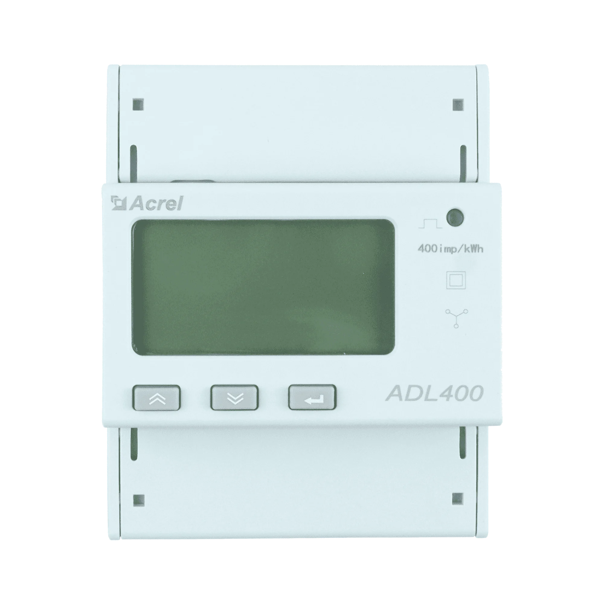
 Design with ADL400 3 phase AC energy meter direct current in Cirkit Designer
Introduction
The ADL400 is a 3-phase AC energy meter manufactured by Acrel, designed for precise measurement and monitoring of electrical energy in industrial and commercial applications. This direct current energy meter is capable of measuring active energy, reactive energy, voltage, current, power, and other electrical parameters. It is widely used in energy management systems, power distribution monitoring, and load analysis.
Explore Projects Built with ADL400 3 phase AC energy meter direct current
 Open Project in Cirkit Designer
 Open Project in Cirkit Designer
 Open Project in Cirkit Designer
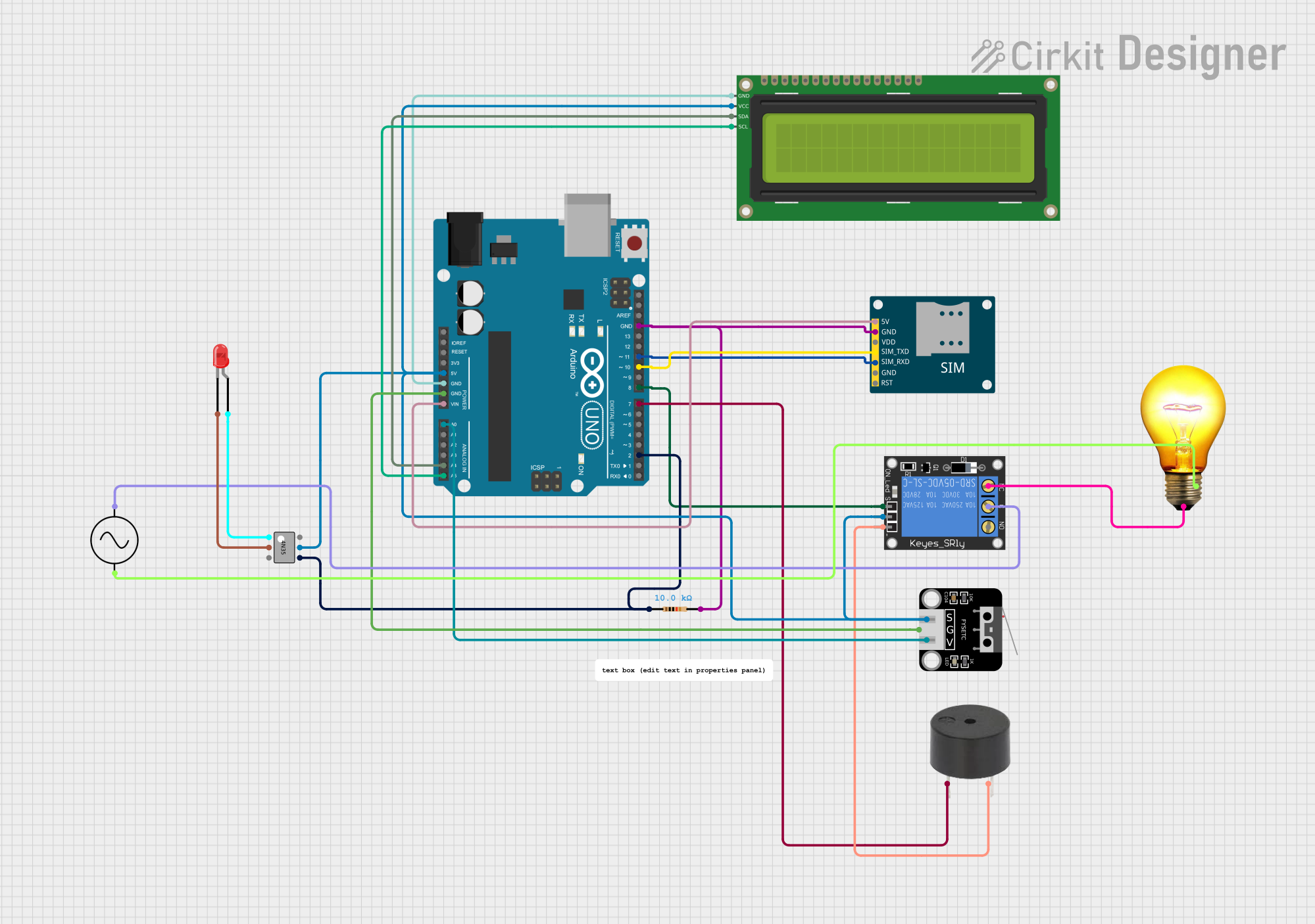 Open Project in Cirkit Designer
Explore Projects Built with ADL400 3 phase AC energy meter direct current
Open Project in Cirkit DesignerOpen Project in Cirkit DesignerOpen Project in Cirkit DesignerOpen Project in Cirkit DesignerCommon Applications
- Industrial energy monitoring and management
- Commercial building power distribution systems
- Renewable energy systems (e.g., solar and wind power)
- Load analysis and optimization in factories
- Sub-metering in multi-tenant buildings
Technical Specifications
Key Technical Details
| Parameter | Specification |
|---|---|
| Manufacturer | Acrel |
| Part ID | ADL400 |
| Measurement Type | 3-phase AC energy meter |
| Voltage Range | 3 × 220V/380V AC |
| Current Range | 1.5(6)A or 10(100)A |
| Frequency | 50Hz/60Hz |
| Accuracy Class | Class 0.5S (active energy) |
| Communication Interface | RS485, Modbus-RTU protocol |
| Power Supply | 85V~265V AC/DC |
| Display | LCD with backlight |
| Operating Temperature | -25°C to +55°C |
| Dimensions | 100mm × 72mm × 65mm |
| Mounting Type | DIN rail |
Pin Configuration and Descriptions
The ADL400 features terminal connections for power input, current transformers (CTs), and communication. Below is the pin configuration:
Power and Measurement Terminals
| Terminal No. | Description |
|---|---|
| 1, 2, 3 | Phase A, B, C voltage input |
| 4 | Neutral (N) input |
| 5, 6 | Phase A current input (CT) |
| 7, 8 | Phase B current input (CT) |
| 9, 10 | Phase C current input (CT) |
Communication Terminals
| Terminal No. | Description |
|---|---|
| 11 | RS485 A+ |
| 12 | RS485 B- |
Auxiliary Power Terminals
| Terminal No. | Description |
|---|---|
| 13, 14 | Auxiliary power input (L, N) |
Usage Instructions
How to Use the ADL400 in a Circuit
- Mounting: Install the ADL400 on a DIN rail in a suitable enclosure to protect it from dust and moisture.
- Wiring:
- Connect the voltage inputs (terminals 1, 2, 3, and 4) to the corresponding phases and neutral of the 3-phase system.
- Connect the current transformers (CTs) to terminals 5-10, ensuring correct polarity.
- Provide auxiliary power to terminals 13 and 14.
- Communication:
- Connect the RS485 communication lines to terminals 11 (A+) and 12 (B-).
- Use the Modbus-RTU protocol for data acquisition and integration with energy management systems.
- Configuration:
- Use the front-panel buttons to configure parameters such as CT ratio, communication address, and baud rate.
- Refer to the user manual for detailed configuration steps.
Important Considerations and Best Practices
- Ensure the CTs are installed with the correct orientation to avoid measurement errors.
- Verify that the voltage and current inputs match the meter's rated specifications.
- Use shielded twisted-pair cables for RS485 communication to minimize interference.
- Avoid exposing the meter to extreme temperatures or humidity.
- Regularly calibrate the meter to maintain accuracy.
Arduino UNO Integration Example
The ADL400 can be connected to an Arduino UNO via the RS485 interface for data logging and monitoring. Below is an example code snippet for reading data using the Modbus-RTU protocol:
#include <ModbusMaster.h>

// Instantiate ModbusMaster object
ModbusMaster node;

void setup() {
  Serial.begin(9600); // Initialize serial communication
  node.begin(1, Serial); // Set Modbus slave ID to 1
}

void loop() {
  uint8_t result;
  uint16_t data[2];

  // Read active energy (register address 0x0000)
  result = node.readInputRegisters(0x0000, 2);
  if (result == node.ku8MBSuccess) {
    data[0] = node.getResponseBuffer(0); // High word
    data[1] = node.getResponseBuffer(1); // Low word
    float activeEnergy = (data[0] << 16 | data[1]) * 0.01; // Convert to kWh
    Serial.print("Active Energy: ");
    Serial.print(activeEnergy);
    Serial.println(" kWh");
  } else {
    Serial.println("Failed to read data");
  }

  delay(1000); // Wait 1 second before next read
}
Notes:
- Use an RS485-to-TTL converter to interface the ADL400 with the Arduino UNO.
- Adjust the Modbus slave ID and register addresses as per your configuration.
Troubleshooting and FAQs
Common Issues and Solutions
No Display on the Meter:
- Check the auxiliary power supply connections (terminals 13 and 14).
- Ensure the supply voltage is within the specified range (85V~265V AC/DC).
Incorrect Energy Readings:
- Verify the CT connections and polarity.
- Ensure the CT ratio is correctly configured in the meter settings.
Communication Failure:
- Check the RS485 wiring for loose or incorrect connections.
- Ensure the Modbus slave ID and baud rate match the configuration in your software.
Meter Not Responding to Commands:
- Confirm that the Modbus address and register values are correct.
- Use a Modbus diagnostic tool to test communication.
FAQs
Q: Can the ADL400 measure single-phase systems?
A: Yes, the ADL400 can measure single-phase systems by connecting only one phase and neutral.
Q: What is the maximum cable length for RS485 communication?
A: The maximum recommended cable length for RS485 is 1200 meters, using shielded twisted-pair cables.
Q: How often should the meter be calibrated?
A: Calibration frequency depends on usage, but it is recommended to calibrate annually for optimal accuracy.
Q: Can the ADL400 store historical data?
A: No, the ADL400 does not have onboard data storage. Use an external data logger or energy management system for historical data.
This concludes the documentation for the ADL400 3-phase AC energy meter. For further assistance, refer to the manufacturer's user manual or contact Acrel support.