Cirkit Designer Logo
Cirkit Designer
Your all-in-one circuit design IDE
Home / 
Component Documentation

How to Use 5V PSU: Examples, Pinouts, and Specs

Image of 5V PSU
Cirkit Designer LogoDesign with 5V PSU in Cirkit Designer

5V Power Supply Unit (PSU) Documentation

1. Introduction

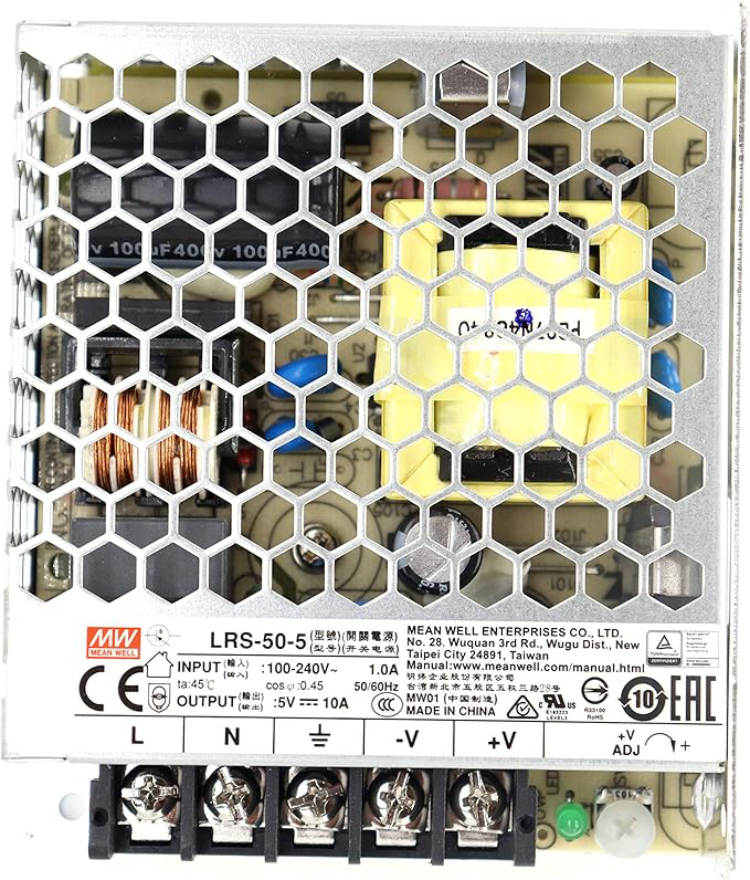
A 5V Power Supply Unit (PSU) is an essential electronic component designed to provide a stable and regulated 5-volt output. It is widely used in powering low-voltage electronic circuits, microcontrollers, sensors, and other devices that require a consistent 5V DC supply for reliable operation. The PSU ensures that connected devices receive a steady voltage, protecting them from fluctuations and potential damage caused by unstable power sources.

Common Applications:

  • Powering microcontrollers (e.g., Arduino, Raspberry Pi)
  • Supplying power to sensors, actuators, and modules
  • Driving small DC motors and LEDs
  • Providing a stable voltage source for breadboard prototyping
  • Charging low-power USB devices

2. Technical Specifications

The following table outlines the key technical details of the 5V PSU:

Parameter Value
Input Voltage Range 7V - 12V DC (typical)
Output Voltage 5V DC (regulated)
Output Current Up to 1A (depending on model)
Ripple Voltage < 50mV
Efficiency ~85%
Protection Features Overvoltage, Overcurrent, Short Circuit
Operating Temperature -20°C to +70°C
Dimensions Varies by model (e.g., 25mm x 20mm)

Pin Configuration and Descriptions

Pin Name Description
VIN Input voltage pin (connect 7-12V DC)
GND Ground pin (common ground for input and output)
VOUT Regulated 5V output pin

3. Usage Instructions

Connecting the 5V PSU in a Circuit

  1. Input Voltage: Connect a DC power source (7-12V) to the VIN pin. Ensure the input voltage is within the specified range to avoid damaging the PSU.
  2. Ground Connection: Connect the GND pin to the ground of your circuit.
  3. Output Voltage: Use the VOUT pin to supply a stable 5V to your circuit or device.

Important Considerations:

  • Input Voltage Range: Always ensure the input voltage is within the specified range (7-12V). Exceeding this range may damage the PSU.
  • Current Limitations: Do not exceed the maximum output current rating (1A). Overloading the PSU can cause overheating or failure.
  • Heat Dissipation: If the PSU is used near its maximum current rating, ensure proper ventilation or heat sinking to prevent overheating.
  • Polarity: Double-check the polarity of the input and output connections to avoid damage to the PSU or connected devices.

Example Circuit:

Below is an example of how to use the 5V PSU to power an Arduino UNO and an LED:

+-------------------+       +-------------------+
| DC Power Source   |       | Arduino UNO       |
| (7-12V)           |       |                   |
|                   |       |                   |
|   +---- VIN ------+-------+ VIN               |
|   |               |       |                   |
|   +---- GND ------+-------+ GND               |
|                   |       |                   |
+-------------------+       +-------------------+

4. Example Code for Arduino UNO

If you're using the 5V PSU to power an Arduino UNO, you can use the following code to blink an LED connected to pin 13:

// Example code to blink an LED on Arduino UNO
// Ensure the Arduino is powered by the 5V PSU

void setup() {
  pinMode(13, OUTPUT); // Set pin 13 as an output pin
}

void loop() {
  digitalWrite(13, HIGH); // Turn the LED on
  delay(1000);            // Wait for 1 second
  digitalWrite(13, LOW);  // Turn the LED off
  delay(1000);            // Wait for 1 second
}

Notes:

  • Connect the 5V PSU's VOUT pin to the Arduino's VIN pin.
  • Ensure the PSU's GND pin is connected to the Arduino's GND pin.

5. Troubleshooting and FAQs

Common Issues and Solutions

Issue Possible Cause Solution
No output voltage Incorrect input voltage or polarity Verify input voltage and polarity
Output voltage fluctuates Overloading the PSU Reduce the load or check for short circuits
PSU overheating Exceeding current rating or poor ventilation Reduce load or improve heat dissipation
Connected device not working Incorrect wiring or insufficient current Double-check connections and current draw

FAQs

Q1: Can I use the 5V PSU to power a Raspberry Pi?
A1: Yes, but ensure the PSU can provide sufficient current (at least 2.5A for most Raspberry Pi models). The PSU described here may not be suitable for high-power Raspberry Pi models.

Q2: What happens if I connect an input voltage higher than 12V?
A2: Exceeding the input voltage range can damage the PSU. Always use a regulated DC power source within the specified range.

Q3: Can I use the 5V PSU to charge USB devices?
A3: Yes, as long as the device's current requirements do not exceed the PSU's maximum output current (1A).

Q4: How do I know if the PSU is overloaded?
A4: Symptoms of overloading include fluctuating output voltage, overheating, or the PSU shutting down. Reduce the load to resolve the issue.


6. Conclusion

The 5V Power Supply Unit (PSU) is a versatile and reliable component for powering low-voltage electronic devices and circuits. By following the usage instructions and adhering to the technical specifications, you can ensure safe and efficient operation. Whether you're prototyping with an Arduino or powering sensors, the 5V PSU is an indispensable tool for your electronics projects.

Explore Projects Built with 5V PSU

Use Cirkit Designer to design, explore, and prototype these projects online. Some projects support real-time simulation. Click "Open Project" to start designing instantly!
12V to 5V Power Supply with LED Indicator and Push Switch
Image of Power Supply LVCO: A project utilizing 5V PSU in a practical application
This circuit is a 12V to 5V regulated power supply with an LED indicator. It uses a 5408 diode for reverse polarity protection, an LM340T5 7805 voltage regulator to step down the voltage to 5V, and a push switch to control the LED indicator. The circuit also includes capacitors for filtering and a resistor to limit the current through the LED.
Cirkit Designer LogoOpen Project in Cirkit Designer
Battery-Powered USB Charger with LED Indicator and DC Motor
Image of Copy of Hand Crank mobile charger : A project utilizing 5V PSU in a practical application
This circuit converts AC power to DC using a bridge rectifier and regulates the voltage to 5V with a 7805 voltage regulator. It powers a USB port and indicates power status with an LED, while also providing a charging interface through a multi-charging cable.
Cirkit Designer LogoOpen Project in Cirkit Designer
Dual 5V Power Supply Distribution Circuit with Toggle Switch Control
Image of rfdriver: A project utilizing 5V PSU in a practical application
This circuit consists of two 5V 5A power supplies connected to an AC wall plug point, providing DC output through a 12-way connector. The ground connections from both power supplies are interconnected and also connected to the ground pins of two toggle switches. The DC outputs from the power supplies are separately connected to different pins on the 12-way connector, with each power supply output being switchable via one of the toggle switches.
Cirkit Designer LogoOpen Project in Cirkit Designer
USB-Powered DC Gear Motor with LED Indicator
Image of Hand Crank mobile charger : A project utilizing 5V PSU in a practical application
This circuit appears to be a power supply unit with a bridge rectifier connected to a DC gear motor, indicating it is designed to convert AC to DC power for the motor. An electrolytic capacitor is used for smoothing the DC output, and a 7805 voltage regulator is included to provide a stable 5V output. Additionally, there is an LED with a series resistor, likely serving as a power indicator light.
Cirkit Designer LogoOpen Project in Cirkit Designer

Explore Projects Built with 5V PSU

Use Cirkit Designer to design, explore, and prototype these projects online. Some projects support real-time simulation. Click "Open Project" to start designing instantly!
Image of Power Supply LVCO: A project utilizing 5V PSU in a practical application
12V to 5V Power Supply with LED Indicator and Push Switch
This circuit is a 12V to 5V regulated power supply with an LED indicator. It uses a 5408 diode for reverse polarity protection, an LM340T5 7805 voltage regulator to step down the voltage to 5V, and a push switch to control the LED indicator. The circuit also includes capacitors for filtering and a resistor to limit the current through the LED.
Cirkit Designer LogoOpen Project in Cirkit Designer
Image of Copy of Hand Crank mobile charger : A project utilizing 5V PSU in a practical application
Battery-Powered USB Charger with LED Indicator and DC Motor
This circuit converts AC power to DC using a bridge rectifier and regulates the voltage to 5V with a 7805 voltage regulator. It powers a USB port and indicates power status with an LED, while also providing a charging interface through a multi-charging cable.
Cirkit Designer LogoOpen Project in Cirkit Designer
Image of rfdriver: A project utilizing 5V PSU in a practical application
Dual 5V Power Supply Distribution Circuit with Toggle Switch Control
This circuit consists of two 5V 5A power supplies connected to an AC wall plug point, providing DC output through a 12-way connector. The ground connections from both power supplies are interconnected and also connected to the ground pins of two toggle switches. The DC outputs from the power supplies are separately connected to different pins on the 12-way connector, with each power supply output being switchable via one of the toggle switches.
Cirkit Designer LogoOpen Project in Cirkit Designer
Image of Hand Crank mobile charger : A project utilizing 5V PSU in a practical application
USB-Powered DC Gear Motor with LED Indicator
This circuit appears to be a power supply unit with a bridge rectifier connected to a DC gear motor, indicating it is designed to convert AC to DC power for the motor. An electrolytic capacitor is used for smoothing the DC output, and a 7805 voltage regulator is included to provide a stable 5V output. Additionally, there is an LED with a series resistor, likely serving as a power indicator light.
Cirkit Designer LogoOpen Project in Cirkit Designer