Cirkit Designer
Your all-in-one circuit design IDE
Home /
Component Documentation
How to Use WATER SENSOR 2: Examples, Pinouts, and Specs

Introduction
The WATER SENSOR 2 is a device designed to detect the presence of water. It is commonly used in applications such as leak detection, water level monitoring, and environmental sensing. This sensor is ideal for projects requiring real-time water detection and is compatible with microcontrollers like Arduino, Raspberry Pi, and other development boards.
Explore Projects Built with WATER SENSOR 2
Arduino-Controlled Bluetooth Water Sensor with Servo and LED Indicators
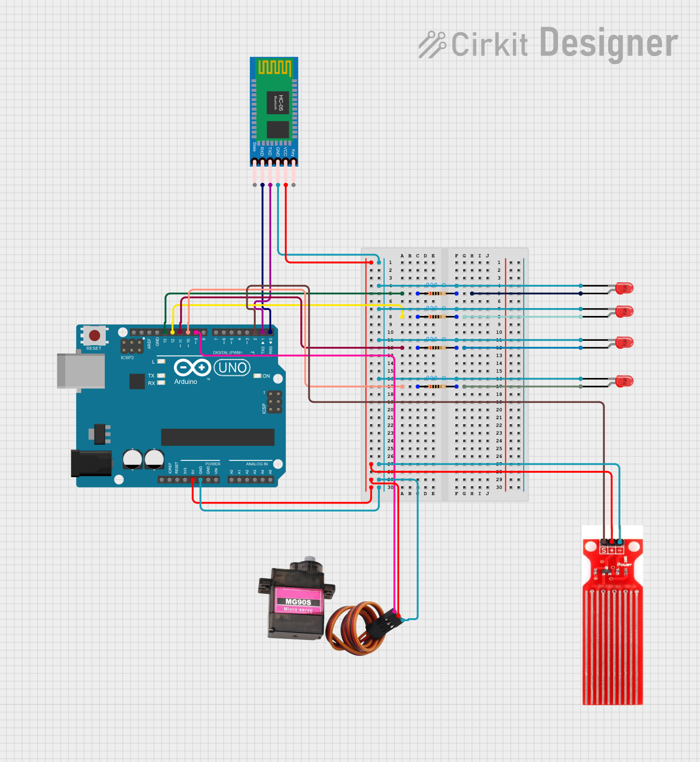
This is a microcontroller-based system designed to monitor water presence using a sensor and communicate wirelessly via Bluetooth. It includes visual indicators (LEDs) and a servo motor for responsive actions, all controlled by an Arduino UNO.
Arduino-Powered GSM Water Quality Monitoring and Pump Control System
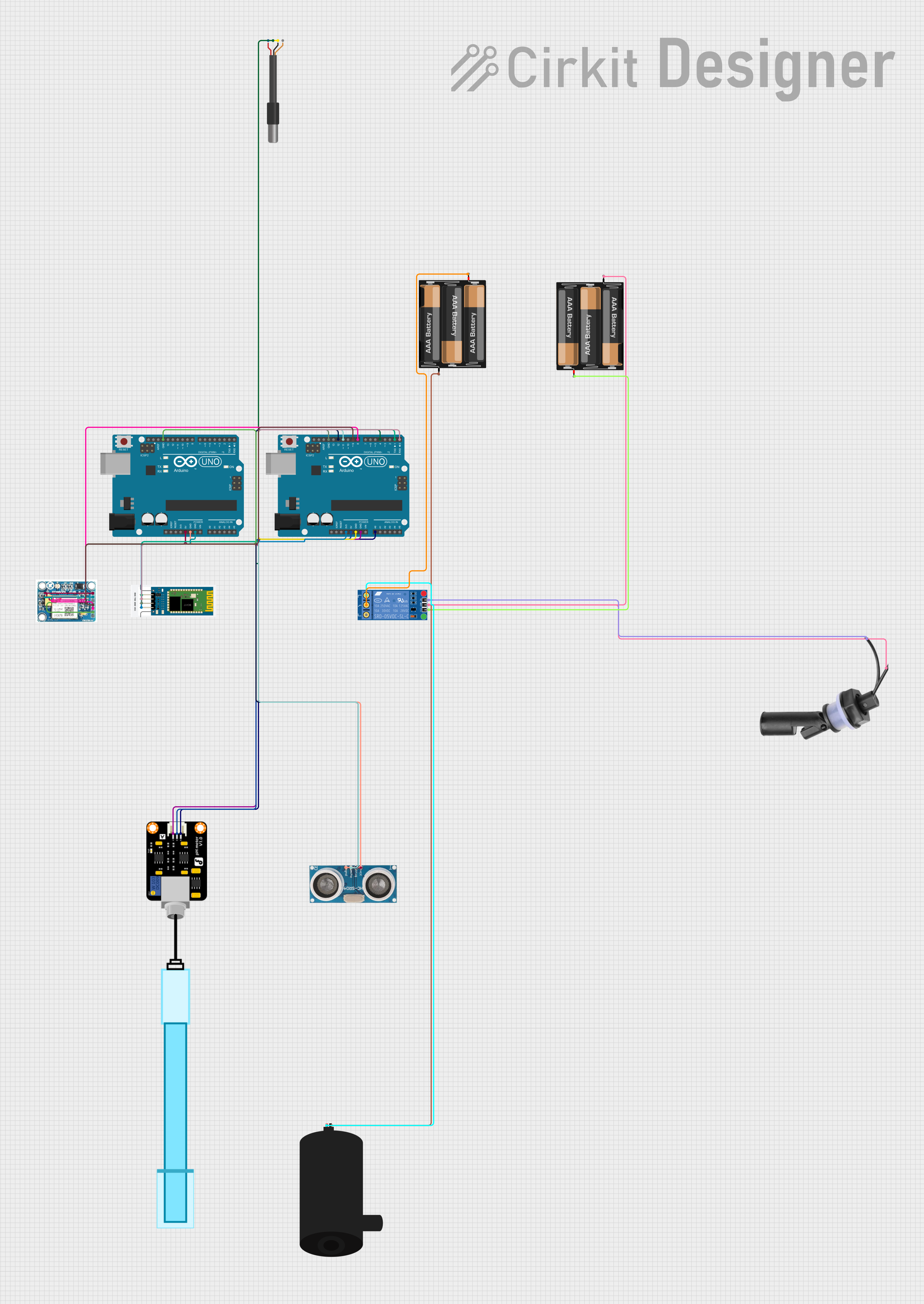
This is a sensor and control system with remote communication capabilities. It monitors temperature, pH levels, and water levels, and controls a water pump based on the float switch status. Data can be accessed and the system can be controlled remotely via Bluetooth and GSM modules connected to two Arduino UNO microcontrollers.
Arduino UNO Flood Management System with Ultrasonic Sensor and Wi-Fi Connectivity
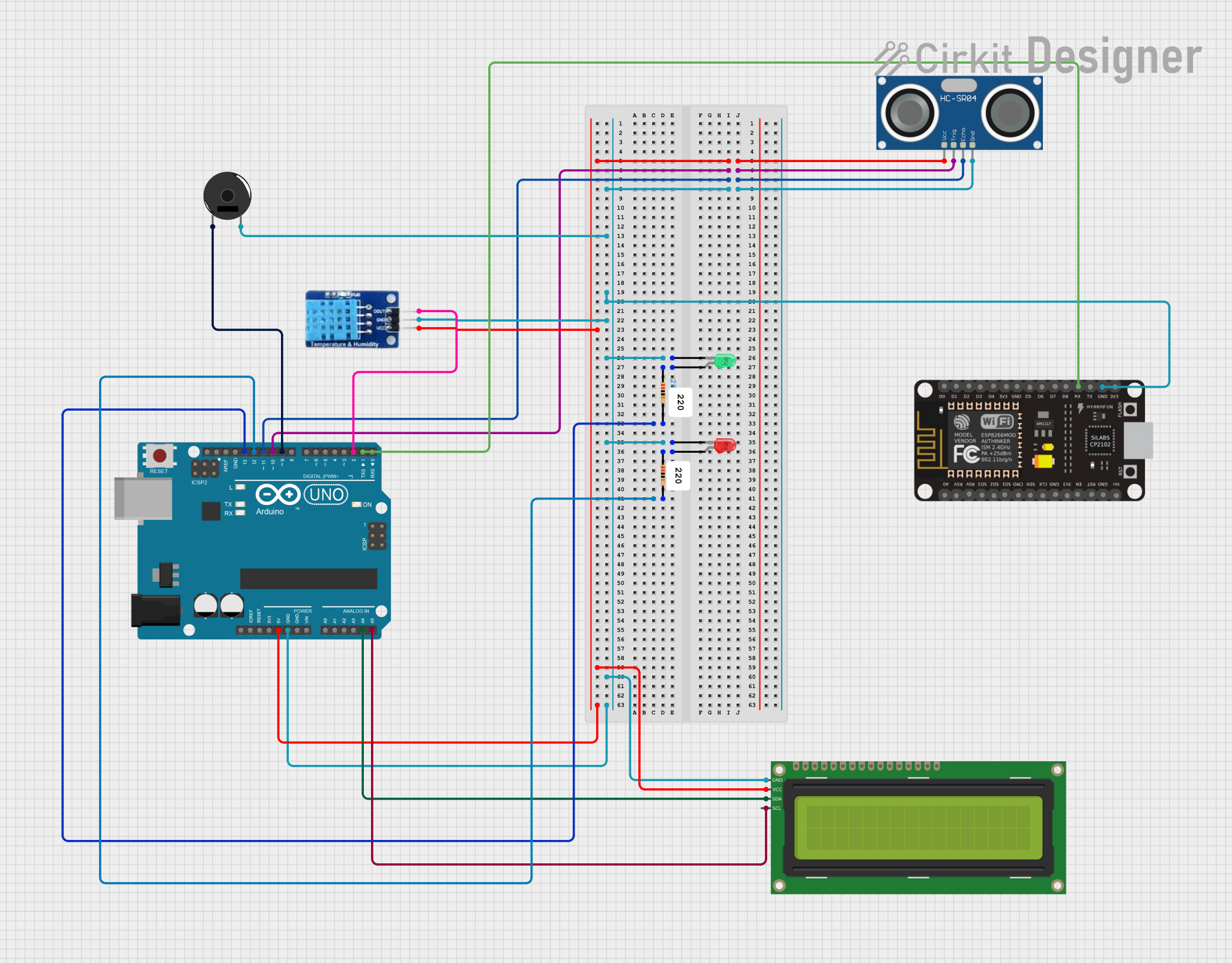
This circuit is a flood management system that uses an Arduino UNO to monitor water levels, temperature, and humidity. It employs an HC-SR04 ultrasonic sensor for distance measurement, a DHT11 sensor for temperature and humidity, and displays the data on a 16x2 I2C LCD. Additionally, it includes a piezo buzzer and LEDs to provide alerts when water levels exceed a safety threshold.
Arduino UNO Based Multi-Sensor Monitoring System with LCD Feedback and Alert Buzzer
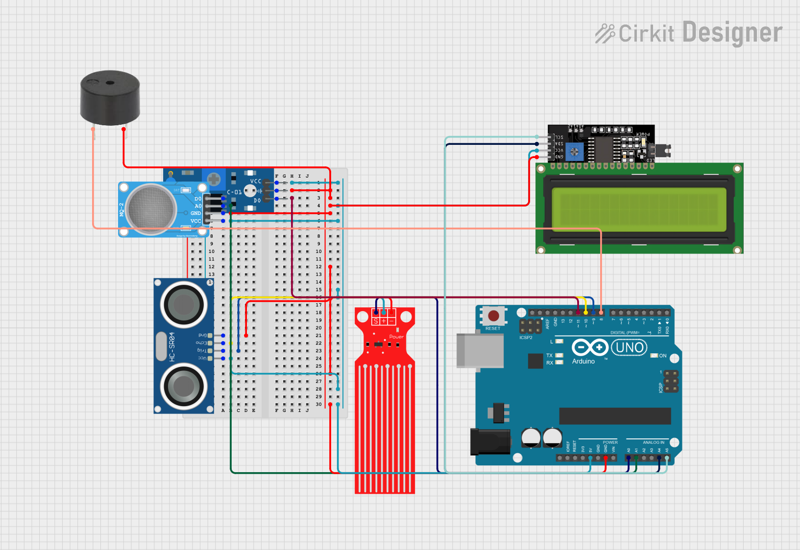
This circuit is designed for environmental monitoring and includes an Arduino UNO as the central microcontroller. It features a water level sensor, an HC-SR04 ultrasonic sensor for distance measurement, an MQ-2 gas sensor, a SW-420 vibration sensor, and a buzzer for alerts. The system outputs sensor readings to an LCD display and triggers the buzzer if any sensor reading exceeds predefined thresholds, indicating potential hazards such as high water level, close proximity of objects, excessive gas concentration, or vibrations.
Explore Projects Built with WATER SENSOR 2
Arduino-Controlled Bluetooth Water Sensor with Servo and LED Indicators
This is a microcontroller-based system designed to monitor water presence using a sensor and communicate wirelessly via Bluetooth. It includes visual indicators (LEDs) and a servo motor for responsive actions, all controlled by an Arduino UNO.
Arduino-Powered GSM Water Quality Monitoring and Pump Control System
This is a sensor and control system with remote communication capabilities. It monitors temperature, pH levels, and water levels, and controls a water pump based on the float switch status. Data can be accessed and the system can be controlled remotely via Bluetooth and GSM modules connected to two Arduino UNO microcontrollers.
Arduino UNO Flood Management System with Ultrasonic Sensor and Wi-Fi Connectivity
This circuit is a flood management system that uses an Arduino UNO to monitor water levels, temperature, and humidity. It employs an HC-SR04 ultrasonic sensor for distance measurement, a DHT11 sensor for temperature and humidity, and displays the data on a 16x2 I2C LCD. Additionally, it includes a piezo buzzer and LEDs to provide alerts when water levels exceed a safety threshold.
Arduino UNO Based Multi-Sensor Monitoring System with LCD Feedback and Alert Buzzer
This circuit is designed for environmental monitoring and includes an Arduino UNO as the central microcontroller. It features a water level sensor, an HC-SR04 ultrasonic sensor for distance measurement, an MQ-2 gas sensor, a SW-420 vibration sensor, and a buzzer for alerts. The system outputs sensor readings to an LCD display and triggers the buzzer if any sensor reading exceeds predefined thresholds, indicating potential hazards such as high water level, close proximity of objects, excessive gas concentration, or vibrations.
Technical Specifications
- Operating Voltage: 3.3V to 5V
- Output Type: Digital and Analog
- Output Voltage:
- Digital: High (5V) or Low (0V)
- Analog: Proportional to water level
- Current Consumption: < 20mA
- Dimensions: 62mm x 20mm x 8mm
- Detection Area: Exposed PCB with conductive traces
- Interface: 3-pin header (VCC, GND, Signal)
Pin Configuration and Descriptions
| Pin Name | Description |
|---|---|
| VCC | Power supply input (3.3V to 5V). Connect to the 3.3V or 5V pin of your MCU. |
| GND | Ground connection. Connect to the GND pin of your MCU. |
| Signal | Outputs the sensor reading. Can be connected to an analog or digital pin. |
Usage Instructions
How to Use the WATER SENSOR 2 in a Circuit
Wiring the Sensor:
- Connect the VCC pin of the sensor to the 5V (or 3.3V) pin of your microcontroller.
- Connect the GND pin of the sensor to the GND pin of your microcontroller.
- Connect the Signal pin to an analog or digital input pin on your microcontroller.
Reading the Output:
- Use the analog output to measure the water level. The voltage increases as the water level rises.
- Use the digital output to detect the presence of water. The output will be HIGH (5V) when water is detected and LOW (0V) otherwise.
Example Circuit:
- Place the sensor in the area where water detection is required.
- Ensure the conductive traces on the sensor are exposed to the water for accurate readings.
Important Considerations and Best Practices
- Avoid submerging the entire sensor in water; only the detection area should come into contact with water.
- Ensure the sensor is kept clean and free from debris to maintain accuracy.
- Use pull-up or pull-down resistors if necessary to stabilize the digital output.
- If using the sensor outdoors, protect it from prolonged exposure to moisture to prevent corrosion.
Example Code for Arduino UNO
// WATER SENSOR 2 Example Code for Arduino UNO
// This code reads both the analog and digital outputs of the sensor
// and prints the results to the Serial Monitor.

const int analogPin = A0; // Analog pin connected to the Signal pin
const int digitalPin = 2; // Digital pin connected to the Signal pin

void setup() {
  pinMode(digitalPin, INPUT); // Set digital pin as input
  Serial.begin(9600);         // Initialize serial communication
}

void loop() {
  int analogValue = analogRead(analogPin); // Read analog value
  int digitalValue = digitalRead(digitalPin); // Read digital value

  // Print the sensor readings to the Serial Monitor
  Serial.print("Analog Value: ");
  Serial.print(analogValue); // Analog value indicates water level
  Serial.print(" | Digital Value: ");
  Serial.println(digitalValue); // Digital value indicates water presence

  delay(500); // Wait for 500ms before the next reading
}
Troubleshooting and FAQs
Common Issues and Solutions
No Output from the Sensor:
- Ensure the sensor is properly connected to the microcontroller.
- Verify that the power supply voltage is within the specified range (3.3V to 5V).
- Check for loose or damaged wires.
Inconsistent Readings:
- Clean the sensor's detection area to remove dirt or debris.
- Ensure the sensor is not fully submerged in water, as this may damage it.
Corrosion on the Sensor:
- If the sensor is used in a humid or wet environment, apply a protective coating to the PCB traces.
- Consider using a waterproof enclosure for long-term outdoor use.
Digital Output Always HIGH or LOW:
- Verify the pull-up or pull-down resistor configuration if used.
- Check if the sensor is exposed to water or completely dry.
FAQs
Can the WATER SENSOR 2 detect the exact water level?
- The analog output provides a proportional voltage that can be used to estimate the water level, but it is not highly precise.
Is the sensor waterproof?
- Only the detection area is designed to come into contact with water. The rest of the sensor should remain dry.
Can I use this sensor with a 3.3V microcontroller?
- Yes, the sensor operates within a voltage range of 3.3V to 5V, making it compatible with 3.3V systems.
What is the maximum water depth the sensor can detect?
- The sensor is designed for surface water detection and is not suitable for deep water applications.