Cirkit Designer
Your all-in-one circuit design IDE
Home /
Component Documentation
How to Use Center Shaft Metal Geared Motor: Examples, Pinouts, and Specs
Introduction
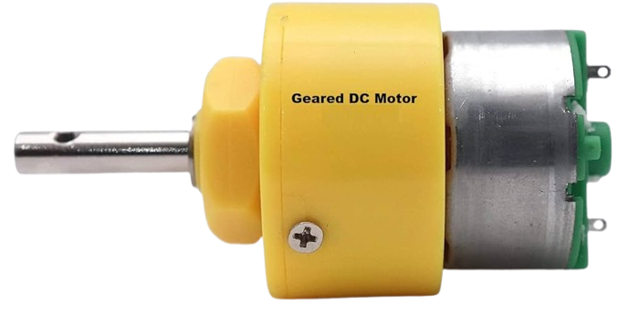
The Center Shaft Metal Geared Motor is a robust and versatile motor designed to deliver high torque and precise control. Equipped with a metal gearbox and a central shaft, this motor is ideal for applications requiring reliable and efficient mechanical movement. Common use cases include robotics, automation systems, conveyor belts, and other machinery where precise control and high torque are essential.
Explore Projects Built with Center Shaft Metal Geared Motor
Battery-Powered Motor Control Circuit with LED Indicators
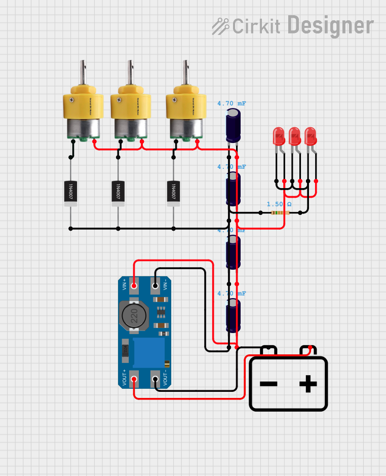
This circuit consists of three Center Shaft Metal Geared Motors, each protected by a 1N4007 Rectifier Diode, and powered by a 12V battery through an MT3608 boost converter. The circuit also includes multiple electrolytic capacitors for filtering and three red LEDs with a current-limiting resistor, indicating the operational status of the motors.
Battery-Powered DPDT Switch Controlled Motor System
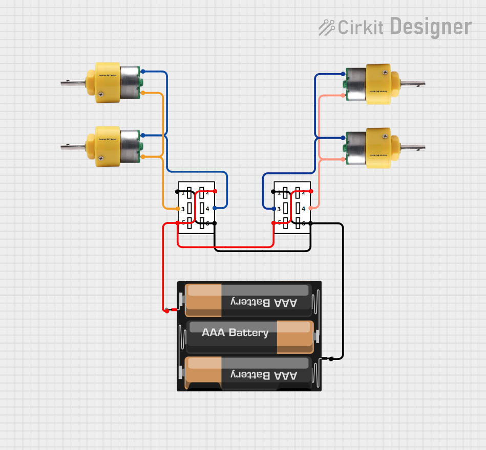
This circuit uses two DPDT switches to control the direction of four center shaft metal geared motors powered by a 3xAA battery pack. The switches allow for reversing the polarity of the motors, enabling forward and reverse motion.
Battery-Powered Directional Control for 12V Geared Motors
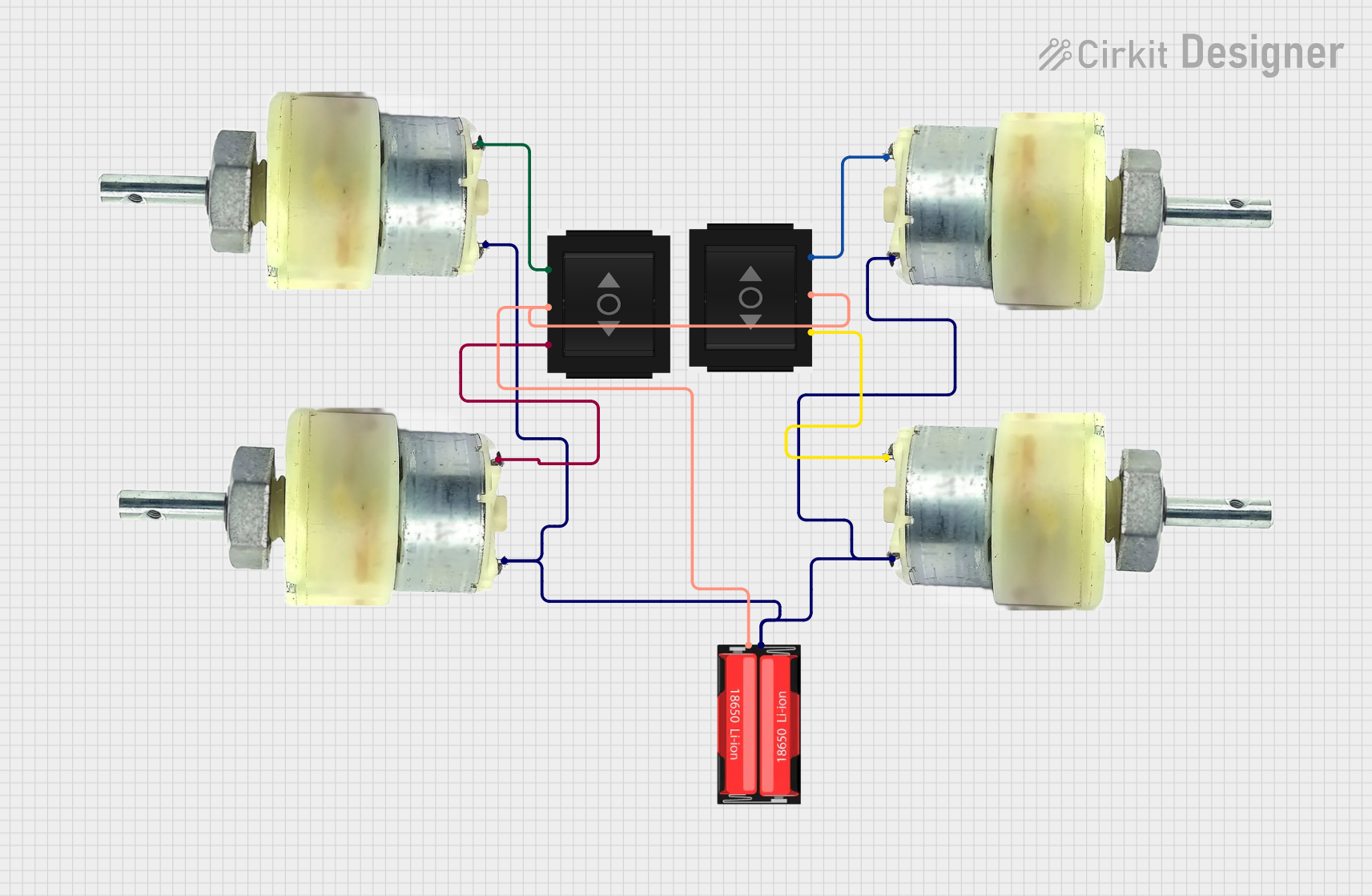
This circuit consists of four 12V geared motors and two directional switches, all powered by a single 18650 Li-Ion battery. The directional switches are used to control the polarity of the voltage applied to the motors, allowing for the reversal of motor direction. The battery's negative terminal is connected to one terminal of each motor, while its positive terminal is connected to the input of both directional switches, which then selectively power the other terminals of the motors.
Arduino UNO Controlled Gear Motor and Servo System with Integrated Encoder
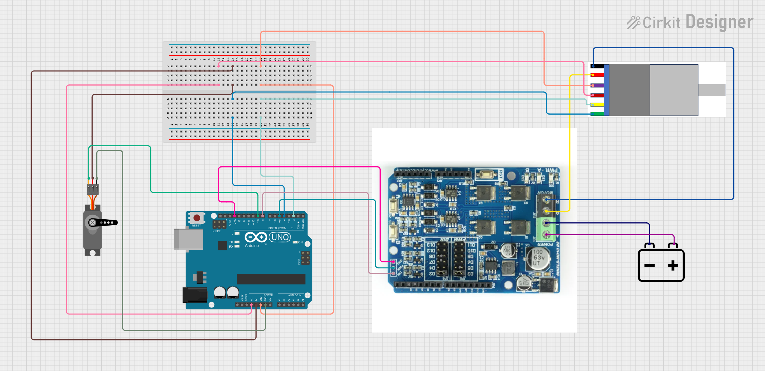
This circuit controls a gear motor with an integrated encoder and a servo motor using an Arduino UNO. The Arduino reads encoder signals to measure the motor's speed and direction, and it can control the motor's speed and direction via a Cytron MD-10 motor driver. Additionally, the Arduino controls the position of a servo motor.
Explore Projects Built with Center Shaft Metal Geared Motor
Battery-Powered Motor Control Circuit with LED Indicators
This circuit consists of three Center Shaft Metal Geared Motors, each protected by a 1N4007 Rectifier Diode, and powered by a 12V battery through an MT3608 boost converter. The circuit also includes multiple electrolytic capacitors for filtering and three red LEDs with a current-limiting resistor, indicating the operational status of the motors.
Battery-Powered DPDT Switch Controlled Motor System
This circuit uses two DPDT switches to control the direction of four center shaft metal geared motors powered by a 3xAA battery pack. The switches allow for reversing the polarity of the motors, enabling forward and reverse motion.
Battery-Powered Directional Control for 12V Geared Motors
This circuit consists of four 12V geared motors and two directional switches, all powered by a single 18650 Li-Ion battery. The directional switches are used to control the polarity of the voltage applied to the motors, allowing for the reversal of motor direction. The battery's negative terminal is connected to one terminal of each motor, while its positive terminal is connected to the input of both directional switches, which then selectively power the other terminals of the motors.
Arduino UNO Controlled Gear Motor and Servo System with Integrated Encoder
This circuit controls a gear motor with an integrated encoder and a servo motor using an Arduino UNO. The Arduino reads encoder signals to measure the motor's speed and direction, and it can control the motor's speed and direction via a Cytron MD-10 motor driver. Additionally, the Arduino controls the position of a servo motor.
Technical Specifications
Key Technical Details
| Parameter | Value |
|---|---|
| Operating Voltage | 6V - 12V |
| Rated Current | 0.5A - 1.2A |
| Stall Current | 2.5A |
| Rated Torque | 1.5 kg.cm - 5 kg.cm |
| Stall Torque | 10 kg.cm |
| Gear Ratio | 1:30, 1:50, 1:100 (varies) |
| Shaft Diameter | 6mm |
| Shaft Length | 20mm |
| Motor Dimensions | 50mm x 25mm x 25mm |
| Weight | 150g |
Pin Configuration and Descriptions
| Pin Number | Pin Name | Description |
|---|---|---|
| 1 | VCC | Power supply (6V - 12V) |
| 2 | GND | Ground |
| 3 | IN1 | Motor control input 1 |
| 4 | IN2 | Motor control input 2 |
Usage Instructions
How to Use the Component in a Circuit
To use the Center Shaft Metal Geared Motor in a circuit, follow these steps:
- Power Supply: Connect the VCC pin to a power supply within the operating voltage range (6V - 12V). Connect the GND pin to the ground of the power supply.
- Motor Control: Use a motor driver (e.g., L298N) to control the motor. Connect the IN1 and IN2 pins to the motor driver's output pins.
- Arduino Connection: If using an Arduino UNO, connect the motor driver's input pins to the Arduino's digital pins.
Important Considerations and Best Practices
- Power Supply: Ensure the power supply can provide sufficient current to avoid motor stalling.
- Heat Dissipation: The motor may heat up during operation. Ensure proper ventilation or heat sinks to prevent overheating.
- Load Management: Avoid overloading the motor to prevent damage to the gearbox and motor windings.
- Direction Control: Use the IN1 and IN2 pins to control the motor's direction. Setting IN1 high and IN2 low will rotate the motor in one direction, and vice versa.
Example Code for Arduino UNO
// Example code to control the Center Shaft Metal Geared Motor using Arduino UNO
// and L298N motor driver

const int IN1 = 9; // Motor control input 1
const int IN2 = 10; // Motor control input 2

void setup() {
  pinMode(IN1, OUTPUT); // Set IN1 as an output
  pinMode(IN2, OUTPUT); // Set IN2 as an output
}

void loop() {
  // Rotate motor in one direction
  digitalWrite(IN1, HIGH); // Set IN1 high
  digitalWrite(IN2, LOW); // Set IN2 low
  delay(2000); // Run for 2 seconds

  // Stop the motor
  digitalWrite(IN1, LOW); // Set IN1 low
  digitalWrite(IN2, LOW); // Set IN2 low
  delay(1000); // Stop for 1 second

  // Rotate motor in the opposite direction
  digitalWrite(IN1, LOW); // Set IN1 low
  digitalWrite(IN2, HIGH); // Set IN2 high
  delay(2000); // Run for 2 seconds

  // Stop the motor
  digitalWrite(IN1, LOW); // Set IN1 low
  digitalWrite(IN2, LOW); // Set IN2 low
  delay(1000); // Stop for 1 second
}
Troubleshooting and FAQs
Common Issues Users Might Face
- Motor Not Running: Ensure the power supply is within the specified voltage range and the connections are secure.
- Motor Overheating: Check for proper ventilation and avoid running the motor at stall current for extended periods.
- Inconsistent Speed: Verify the power supply's stability and ensure the motor driver is functioning correctly.
Solutions and Tips for Troubleshooting
- Check Connections: Ensure all connections are secure and correctly oriented.
- Measure Voltage: Use a multimeter to measure the voltage at the motor terminals to ensure it is within the specified range.
- Inspect Motor Driver: Ensure the motor driver is not damaged and is capable of handling the motor's current requirements.
- Load Adjustment: Reduce the load on the motor to prevent stalling and overheating.
By following this documentation, users can effectively integrate and utilize the Center Shaft Metal Geared Motor in their projects, ensuring reliable and efficient performance.