
How to Use DC-DC Buck LM2596 3A LED: Examples, Pinouts, and Specs
 Design with DC-DC Buck LM2596 3A LED in Cirkit Designer
Introduction
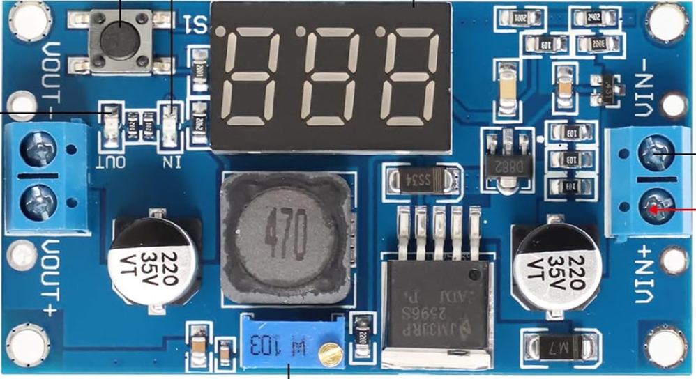
The DC-DC Buck LM2596 3A LED module is a step-down voltage regulator designed to efficiently convert a higher input voltage to a lower output voltage. It is based on the LM2596 buck converter IC and is capable of delivering up to 3A of output current. This module is widely used in applications requiring stable and adjustable DC voltage, such as powering microcontrollers, LED strips, and other low-voltage devices.
Common applications include:
- Powering Arduino, Raspberry Pi, and other development boards
- Battery-powered projects requiring voltage regulation
- LED lighting systems
- DIY electronics and prototyping
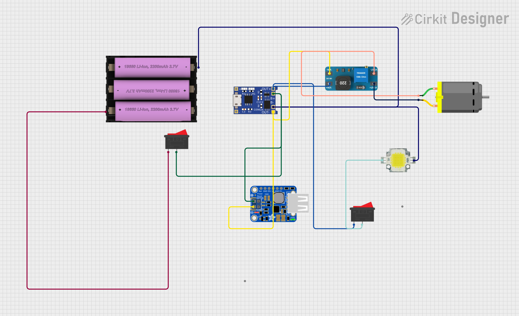
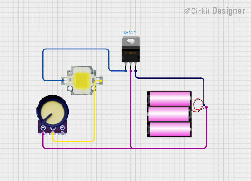
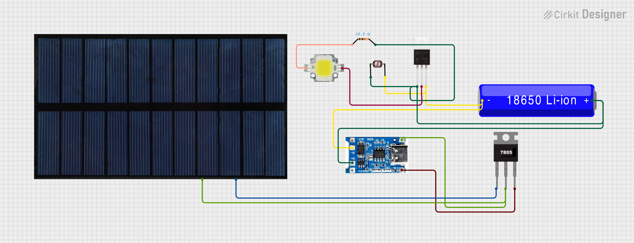
Explore Projects Built with DC-DC Buck LM2596 3A LED
 Open Project in Cirkit Designer
 Open Project in Cirkit Designer
 Open Project in Cirkit Designer
 Open Project in Cirkit Designer
Explore Projects Built with DC-DC Buck LM2596 3A LED
Open Project in Cirkit DesignerOpen Project in Cirkit DesignerOpen Project in Cirkit DesignerOpen Project in Cirkit DesignerTechnical Specifications
- Input Voltage Range: 4V to 40V DC
- Output Voltage Range: 1.25V to 37V DC (adjustable via potentiometer)
- Output Current: Up to 3A (with proper heat dissipation)
- Efficiency: Up to 92% (depending on input/output voltage and load)
- Switching Frequency: 150 kHz
- Voltage Regulation: ±0.5%
- Load Regulation: ±0.5%
- Operating Temperature: -40°C to +85°C
- Dimensions: Typically 43mm x 21mm x 14mm
Pin Configuration and Descriptions
| Pin Name | Description |
|---|---|
| VIN | Positive input voltage (4V to 40V DC). Connect to the power source. |
| GND | Ground connection. Common ground for input and output. |
| VOUT | Positive output voltage (1.25V to 37V DC). Connect to the load. |
| Potentiometer | Adjustable screw to set the output voltage. Rotate clockwise to increase voltage and counterclockwise to decrease voltage. |
Usage Instructions
How to Use the DC-DC Buck LM2596 3A LED Module
Connect the Input Voltage:
- Connect the positive terminal of your power source to the VIN pin.
- Connect the negative terminal of your power source to the GND pin.
- Ensure the input voltage is within the specified range (4V to 40V DC).
Adjust the Output Voltage:
- Use a multimeter to measure the output voltage across the VOUT and GND pins.
- Rotate the potentiometer to adjust the output voltage to the desired level.
Connect the Load:
- Connect the positive terminal of your load to the VOUT pin.
- Connect the negative terminal of your load to the GND pin.
Verify Connections:
- Double-check all connections to ensure proper polarity and secure wiring.
Important Considerations and Best Practices
- Heat Dissipation: For currents above 2A, ensure proper heat dissipation by attaching a heatsink to the LM2596 IC or using active cooling.
- Input Voltage: Always ensure the input voltage is at least 1.5V higher than the desired output voltage for proper regulation.
- Current Limit: Do not exceed the 3A current limit to avoid damaging the module.
- Short Circuit Protection: The module does not have built-in short circuit protection. Use external fuses or protection circuits if necessary.
- Arduino Compatibility: The module can be used to power Arduino boards by setting the output voltage to 5V or 3.3V, depending on the board's requirements.
Example: Powering an Arduino UNO
To power an Arduino UNO using the LM2596 module:
- Set the output voltage to 5V using the potentiometer.
- Connect the VOUT pin to the Arduino's 5V pin.
- Connect the GND pin to the Arduino's GND pin.
Sample Arduino Code for Testing
// This code blinks an LED connected to pin 13 of the Arduino UNO.
// Ensure the LM2596 module is providing a stable 5V to the Arduino.

void setup() {
  pinMode(13, OUTPUT); // Set pin 13 as an output pin
}

void loop() {
  digitalWrite(13, HIGH); // Turn the LED on
  delay(1000);            // Wait for 1 second
  digitalWrite(13, LOW);  // Turn the LED off
  delay(1000);            // Wait for 1 second
}
Troubleshooting and FAQs
Common Issues and Solutions
No Output Voltage:
- Check the input voltage to ensure it is within the specified range.
- Verify all connections, especially the polarity of the input and output terminals.
- Ensure the potentiometer is not set to the minimum output voltage.
Overheating:
- Reduce the load current if it exceeds 2A.
- Attach a heatsink to the LM2596 IC for better heat dissipation.
- Ensure proper ventilation around the module.
Output Voltage Fluctuations:
- Check the input voltage stability. Use a capacitor (e.g., 100µF) across the input terminals if needed.
- Verify the load is not drawing more current than the module's capacity.
Cannot Adjust Output Voltage:
- Ensure the input voltage is at least 1.5V higher than the desired output voltage.
- Check if the potentiometer is functioning correctly.
FAQs
Q: Can I use this module to charge a battery?
A: Yes, but ensure the output voltage is set to the battery's charging voltage, and use a current-limiting circuit if required.
Q: Is the module waterproof?
A: No, the module is not waterproof. Use it in a dry environment or enclose it in a waterproof case.
Q: Can I use this module with a solar panel?
A: Yes, as long as the solar panel's output voltage is within the module's input range. Use a capacitor to stabilize the input voltage if necessary.
Q: Does the module have reverse polarity protection?
A: No, the module does not have reverse polarity protection. Always double-check the polarity before connecting the power source.