How to Use TB9051FTG Single Motor Driver: Examples, Pinouts, and Specs
Introduction
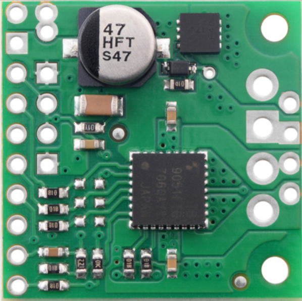
The TB9051FTG is a high-performance motor driver IC manufactured by Pololu. It is designed to control a single DC motor with advanced features such as PWM (Pulse Width Modulation) control, current sensing, and thermal protection. This motor driver is ideal for applications requiring precise motor control, including robotics, automation systems, and industrial equipment.
Explore Projects Built with TB9051FTG Single Motor Driver


Explore Projects Built with TB9051FTG Single Motor Driver
Common Applications and Use Cases
- Robotics and mechatronics projects
- Automated conveyor systems
- Remote-controlled vehicles
- Industrial motor control
- Educational and hobbyist projects
Technical Specifications
The following table outlines the key technical specifications of the TB9051FTG motor driver:
| Parameter | Value |
|---|---|
| Operating Voltage Range | 4.5 V to 28 V |
| Maximum Output Current | 2.6 A continuous, 5.0 A peak |
| Control Interface | PWM, DIR (direction control) |
| Logic Voltage Range | 2.7 V to 5.5 V |
| PWM Frequency Range | Up to 20 kHz |
| Built-in Protections | Overcurrent, thermal shutdown, undervoltage lockout |
| Operating Temperature Range | -40°C to +150°C |
| Package Type | HTSSOP-16 |
Pin Configuration and Descriptions
The TB9051FTG comes in a 16-pin HTSSOP package. Below is the pin configuration and description:
| Pin Number | Pin Name | Description |
|---|---|---|
| 1 | VCC | Logic power supply input (2.7 V to 5.5 V) |
| 2 | GND | Ground connection |
| 3 | PWM | PWM input for speed control |
| 4 | DIR | Direction control input |
| 5 | STBY | Standby control input (active low) |
| 6 | VREF | Reference voltage input for current sensing |
| 7 | CSO | Current sense output |
| 8 | NC | No connection |
| 9 | OUT1 | Motor output 1 |
| 10 | OUT2 | Motor output 2 |
| 11 | VM | Motor power supply input (4.5 V to 28 V) |
| 12 | NC | No connection |
| 13 | NC | No connection |
| 14 | NC | No connection |
| 15 | NC | No connection |
| 16 | NC | No connection |
Usage Instructions
How to Use the TB9051FTG in a Circuit
Power Connections:
- Connect the motor power supply (4.5 V to 28 V) to the
VMpin. - Connect the logic power supply (2.7 V to 5.5 V) to the
VCCpin. - Ensure a common ground connection between the motor driver and the control system.
- Connect the motor power supply (4.5 V to 28 V) to the
Control Inputs:
- Use the
PWMpin to control the motor speed. A higher duty cycle corresponds to a higher speed. - Use the
DIRpin to control the motor's direction. Logic HIGH and LOW determine the rotation direction. - Pull the
STBYpin HIGH to enable the motor driver. Pull it LOW to put the driver in standby mode.
- Use the
Motor Outputs:
- Connect the motor terminals to the
OUT1andOUT2pins.
- Connect the motor terminals to the
Current Sensing:
- The
CSOpin provides a voltage proportional to the motor current. This can be used for monitoring or feedback.
- The
Decoupling Capacitors:
- Place appropriate decoupling capacitors (e.g., 100 µF and 0.1 µF) near the
VMandVCCpins to reduce noise and stabilize the power supply.
- Place appropriate decoupling capacitors (e.g., 100 µF and 0.1 µF) near the
Important Considerations and Best Practices
- Ensure the motor's current and voltage ratings are within the TB9051FTG's specifications.
- Use a heatsink or proper ventilation if operating near the maximum current limit to prevent overheating.
- Avoid floating inputs; connect unused control pins to a defined logic level (HIGH or LOW).
- Use a fuse or other protection mechanism to safeguard the motor driver and connected components.
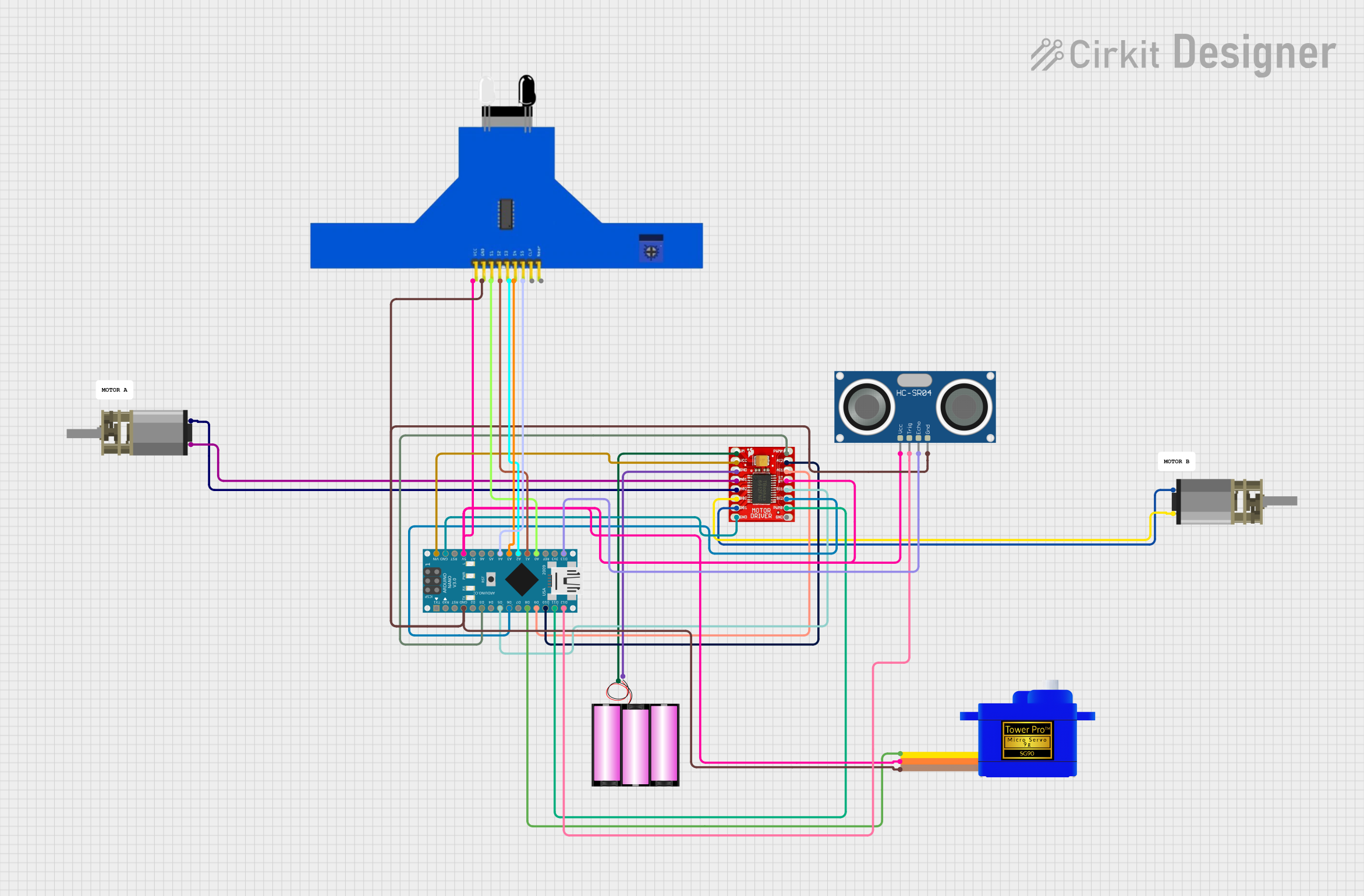
Example: Connecting to an Arduino UNO
The TB9051FTG can be easily controlled using an Arduino UNO. Below is an example code snippet to control motor speed and direction:
// Define motor driver pins
const int PWM_PIN = 9;  // PWM input connected to Arduino pin 9
const int DIR_PIN = 8;  // Direction input connected to Arduino pin 8
const int STBY_PIN = 7; // Standby input connected to Arduino pin 7

void setup() {
  // Set motor driver pins as outputs
  pinMode(PWM_PIN, OUTPUT);
  pinMode(DIR_PIN, OUTPUT);
  pinMode(STBY_PIN, OUTPUT);

  // Enable the motor driver
  digitalWrite(STBY_PIN, HIGH);
}

void loop() {
  // Set motor direction to forward
  digitalWrite(DIR_PIN, HIGH);

  // Set motor speed to 50% (128 out of 255)
  analogWrite(PWM_PIN, 128);

  delay(2000); // Run motor for 2 seconds

  // Set motor direction to reverse
  digitalWrite(DIR_PIN, LOW);

  // Set motor speed to 75% (192 out of 255)
  analogWrite(PWM_PIN, 192);

  delay(2000); // Run motor for 2 seconds
}
Troubleshooting and FAQs
Common Issues and Solutions
Motor Does Not Spin:
- Verify that the
STBYpin is pulled HIGH to enable the motor driver. - Check the power supply connections to
VMandVCC. - Ensure the
PWMsignal is being generated correctly.
- Verify that the
Motor Spins in the Wrong Direction:
- Check the logic level of the
DIRpin. Swap the HIGH and LOW states to reverse the direction.
- Check the logic level of the
Overheating:
- Ensure the motor's current does not exceed the driver's continuous current rating.
- Add a heatsink or improve ventilation around the motor driver.
No Current Sense Output:
- Verify the connection to the
CSOpin. - Ensure the
VREFpin is set to an appropriate reference voltage.
- Verify the connection to the
FAQs
Q: Can the TB9051FTG drive a stepper motor?
A: No, the TB9051FTG is designed for single DC motor control. For stepper motors, use a dedicated stepper motor driver.
Q: What is the maximum PWM frequency supported?
A: The TB9051FTG supports PWM frequencies up to 20 kHz.
Q: Is the TB9051FTG compatible with 3.3 V logic?
A: Yes, the logic voltage range of 2.7 V to 5.5 V makes it compatible with both 3.3 V and 5 V systems.
Q: Can I use the TB9051FTG with a battery-powered system?
A: Yes, as long as the battery voltage is within the operating range of 4.5 V to 28 V for VM and 2.7 V to 5.5 V for VCC.