Cirkit Designer
Your all-in-one circuit design IDE
Home /
Component Documentation
How to Use 5-Way navigation key module: Examples, Pinouts, and Specs
Introduction
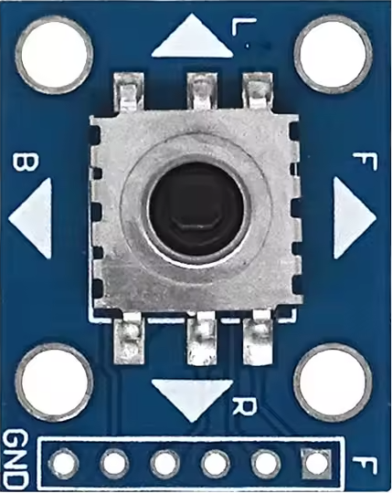
The 5-Way Navigation Key Module is a user interface component designed to provide directional input through a central button and four surrounding buttons. This module is commonly used in various electronic devices, such as remote controls, handheld devices, and user interfaces for embedded systems. Its intuitive design allows users to navigate menus, select options, and control devices with ease.
Explore Projects Built with 5-Way navigation key module
Arduino Nano-Based Portable GSM-GPS Navigator with Compass and Stepper Motor Control

This circuit features an Arduino Nano microcontroller coordinating communication, navigation, and motion control functions. It includes modules for GSM, GPS, and digital compass capabilities, as well as a stepper motor for precise movement, all powered by a LiPo battery with voltage regulation.
WiFi-Controlled Basket-Carrying Robot with GPS and GSM Notification

This circuit is designed for a 4-wheeled WiFi-controlled car with a basket, which uses an ESP8266 NodeMCU microcontroller for logic control. It features an IR sensor for basket full detection, a GPS module for location tracking, and a GSM module (Sim800l) for sending SMS notifications. The L298N motor driver controls four DC gearmotors for movement, and the system is powered by a Li-ion battery with a 7805 voltage regulator providing stable power to the GSM module.
Arduino Nano-Based Panic Button System with GPS and GSM Modules
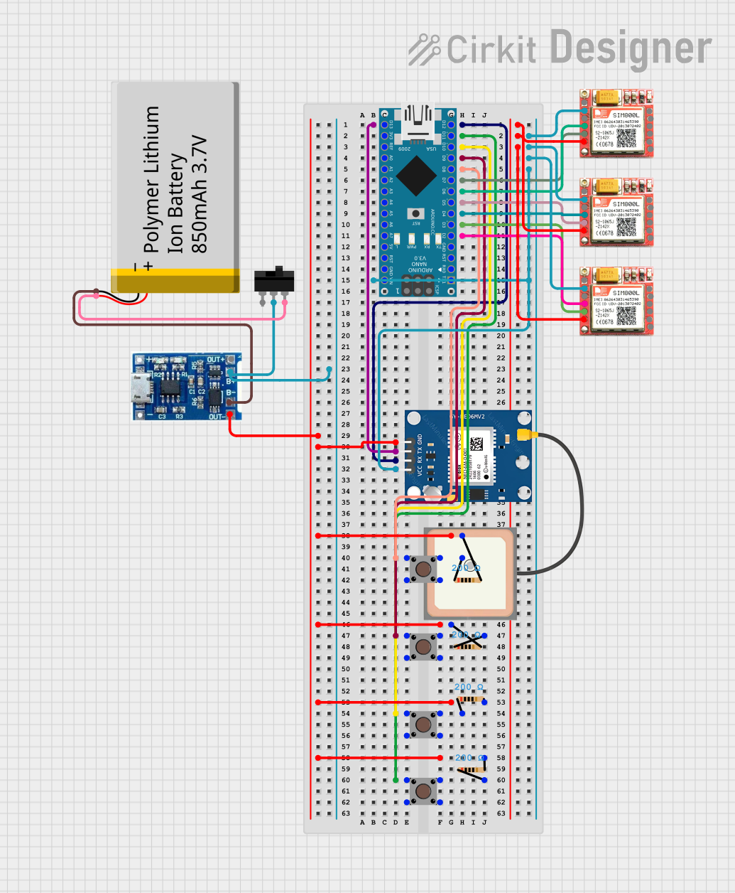
This circuit is designed as a panic button system featuring an Arduino Nano interfaced with a NEO6MV2 GPS module and three SIM800L GSM modules. It includes four pushbuttons, each assigned to trigger a call to a specific emergency service (hospital, fire department, police) or to send the GPS location. The system is powered by a lithium battery with a charging module, and it can send the GPS location to a predefined number or alongside an emergency call when the corresponding buttons are pressed simultaneously.
Arduino Nano-Controlled Servo with I2C LCD Display and Membrane Keypad Interface
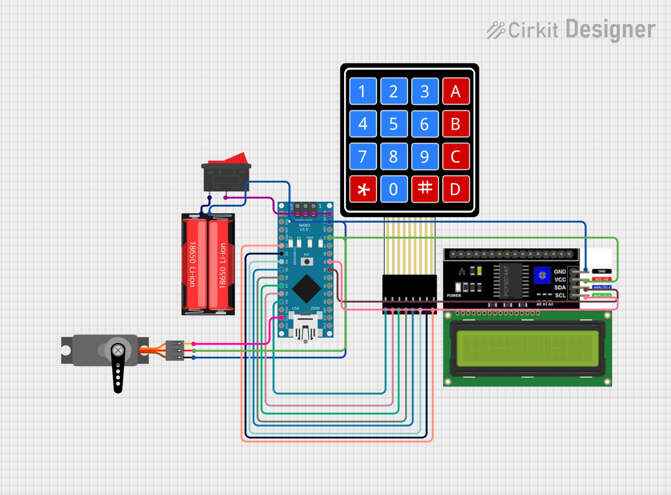
This circuit is designed as an interactive control system featuring an Arduino Nano that interfaces with a 4x4 keypad for input, controls a servo motor, and provides output on an I2C LCD display. A rocker switch and an 18650 Li-Ion battery provide a controlled power source for the system. The circuit is suitable for applications requiring user interaction, visual feedback, and mechanical actuation.
Explore Projects Built with 5-Way navigation key module
Arduino Nano-Based Portable GSM-GPS Navigator with Compass and Stepper Motor Control
This circuit features an Arduino Nano microcontroller coordinating communication, navigation, and motion control functions. It includes modules for GSM, GPS, and digital compass capabilities, as well as a stepper motor for precise movement, all powered by a LiPo battery with voltage regulation.
WiFi-Controlled Basket-Carrying Robot with GPS and GSM Notification
This circuit is designed for a 4-wheeled WiFi-controlled car with a basket, which uses an ESP8266 NodeMCU microcontroller for logic control. It features an IR sensor for basket full detection, a GPS module for location tracking, and a GSM module (Sim800l) for sending SMS notifications. The L298N motor driver controls four DC gearmotors for movement, and the system is powered by a Li-ion battery with a 7805 voltage regulator providing stable power to the GSM module.
Arduino Nano-Based Panic Button System with GPS and GSM Modules
This circuit is designed as a panic button system featuring an Arduino Nano interfaced with a NEO6MV2 GPS module and three SIM800L GSM modules. It includes four pushbuttons, each assigned to trigger a call to a specific emergency service (hospital, fire department, police) or to send the GPS location. The system is powered by a lithium battery with a charging module, and it can send the GPS location to a predefined number or alongside an emergency call when the corresponding buttons are pressed simultaneously.
Arduino Nano-Controlled Servo with I2C LCD Display and Membrane Keypad Interface
This circuit is designed as an interactive control system featuring an Arduino Nano that interfaces with a 4x4 keypad for input, controls a servo motor, and provides output on an I2C LCD display. A rocker switch and an 18650 Li-Ion battery provide a controlled power source for the system. The circuit is suitable for applications requiring user interaction, visual feedback, and mechanical actuation.
Common Applications and Use Cases
- Remote Controls: For navigating channels and settings.
- Embedded Systems: In devices like Arduino projects for user input.
- Menu Navigation: In handheld devices and appliances.
- Gaming Controllers: For directional movement and selection.
Technical Specifications
Key Technical Details
| Specification | Value |
|---|---|
| Operating Voltage | 3.3V to 5V |
| Current Rating | 20mA (max per button) |
| Button Type | Tactile switch |
| Dimensions | 30mm x 30mm x 10mm |
Pin Configuration and Descriptions
| Pin Number | Pin Name | Description |
|---|---|---|
| 1 | Up | Connects to the Up button |
| 2 | Down | Connects to the Down button |
| 3 | Left | Connects to the Left button |
| 4 | Right | Connects to the Right button |
| 5 | Select | Connects to the Central Select button |
| 6 | Ground | Common ground connection |
Usage Instructions
How to Use the Component in a Circuit
- Wiring: Connect the pins of the 5-Way Navigation Key Module to your microcontroller (e.g., Arduino UNO) as per the pin configuration table.
- Power Supply: Ensure the module is powered with a voltage between 3.3V and 5V.
- Pull-Up Resistors: It is recommended to use internal pull-up resistors for the button inputs to avoid floating states.
Important Considerations and Best Practices
- Debouncing: Implement software debouncing to avoid multiple readings from a single button press.
- Testing: Test each button individually to ensure proper functionality.
- Avoid Overcurrent: Do not exceed the maximum current rating of 20mA per button to prevent damage.
Example Arduino Code
Here is a simple example of how to use the 5-Way Navigation Key Module with an Arduino UNO:
// Pin definitions
const int upPin = 2;
const int downPin = 3;
const int leftPin = 4;
const int rightPin = 5;
const int selectPin = 6;

void setup() {
  // Initialize pins as input with pull-up resistors
  pinMode(upPin, INPUT_PULLUP);
  pinMode(downPin, INPUT_PULLUP);
  pinMode(leftPin, INPUT_PULLUP);
  pinMode(rightPin, INPUT_PULLUP);
  pinMode(selectPin, INPUT_PULLUP);

  Serial.begin(9600); // Start serial communication
}

void loop() {
  // Check each button state
  if (digitalRead(upPin) == LOW) {
    Serial.println("Up button pressed");
    delay(200); // Debounce delay
  }
  if (digitalRead(downPin) == LOW) {
    Serial.println("Down button pressed");
    delay(200); // Debounce delay
  }
  if (digitalRead(leftPin) == LOW) {
    Serial.println("Left button pressed");
    delay(200); // Debounce delay
  }
  if (digitalRead(rightPin) == LOW) {
    Serial.println("Right button pressed");
    delay(200); // Debounce delay
  }
  if (digitalRead(selectPin) == LOW) {
    Serial.println("Select button pressed");
    delay(200); // Debounce delay
  }
}
Troubleshooting and FAQs
Common Issues Users Might Face
Buttons Not Responding:
- Ensure proper wiring and connections.
- Check if the module is powered correctly.
Multiple Button Presses Detected:
- Implement debouncing in your code to filter out noise.
Incorrect Button Mapping:
- Verify the pin connections against the pin configuration table.
Solutions and Tips for Troubleshooting
- Use a Multimeter: To check continuity and voltage levels at the pins.
- Test with Simple Code: Start with basic code to isolate issues.
- Check for Shorts: Inspect the module for any soldering or wiring shorts.
By following this documentation, users can effectively integrate the 5-Way Navigation Key Module into their projects, ensuring a smooth and functional user interface experience.