How to Use Relay Automotive 5 Pin: Examples, Pinouts, and Specs
Introduction
The Relay Automotive 5 Pin is an electromechanical switch commonly used in automotive applications. It allows a low-power control signal to switch a high-power circuit, making it ideal for controlling high-current devices such as headlights, horns, motors, and other electrical components. This relay is designed to handle high currents safely and efficiently, ensuring reliable operation in demanding environments.
Explore Projects Built with Relay Automotive 5 Pin


Explore Projects Built with Relay Automotive 5 Pin
Common Applications and Use Cases
- Controlling automotive lighting systems (e.g., headlights, fog lights).
- Activating electric motors (e.g., cooling fans, fuel pumps).
- Switching high-current circuits in car audio systems.
- General-purpose automotive electrical control.
Technical Specifications
The following table outlines the key technical details of the Relay Automotive 5 Pin:
| Parameter | Value |
|---|---|
| Operating Voltage | 12V DC (typical automotive voltage) |
| Coil Resistance | ~85 Ohms |
| Coil Current | ~150 mA |
| Contact Rating | 30A @ 12V DC |
| Contact Configuration | SPDT (Single Pole Double Throw) |
| Operating Temperature | -40°C to +85°C |
| Dimensions | ~28mm x 28mm x 25mm |
Pin Configuration and Descriptions
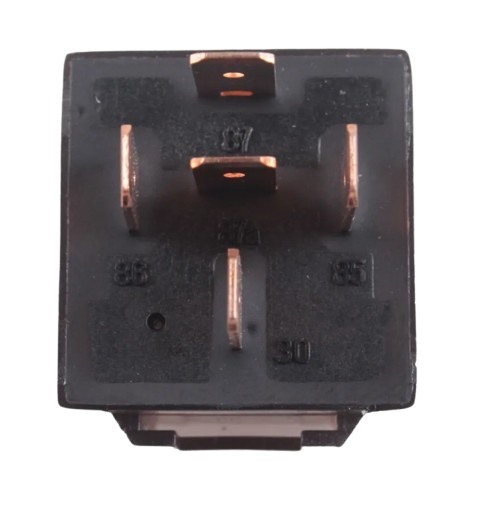
The 5-pin relay has the following pinout:
| Pin Number | Name | Description |
|---|---|---|
| 85 | Coil (-) | Negative terminal of the relay coil. Connect to ground or a low-side driver. |
| 86 | Coil (+) | Positive terminal of the relay coil. Connect to a control signal (e.g., 12V). |
| 30 | Common | Common terminal for the relay switch. Connect to the power source or load. |
| 87 | Normally Open (NO) | Connects to 30 when the relay is activated. Used to power the load. |
| 87a | Normally Closed (NC) | Connects to 30 when the relay is not activated. Used for default state. |
Usage Instructions
How to Use the Relay in a Circuit
- Identify the Pins: Refer to the pin configuration table to locate the coil pins (85 and 86) and the switch pins (30, 87, and 87a).
- Connect the Coil:
- Connect pin 85 to ground (negative terminal of the power source).
- Connect pin 86 to a control signal (e.g., a 12V output from a microcontroller or switch).
- Connect the Load:
- Connect pin 30 to the power source (e.g., battery positive terminal).
- Connect pin 87 to the positive terminal of the load (e.g., a motor or light).
- If using the NC terminal, connect pin 87a to the load instead of pin 87.
- Power the Circuit: When the control signal is applied to the coil (pins 85 and 86), the relay will activate, connecting pin 30 to pin 87 and powering the load.
Important Considerations and Best Practices
- Diode Protection: Add a flyback diode across the coil (pins 85 and 86) to protect the circuit from voltage spikes when the relay is deactivated.
- Current Rating: Ensure the load current does not exceed the relay's contact rating (30A @ 12V DC).
- Secure Connections: Use crimp terminals or soldered connections for reliable operation in automotive environments.
- Mounting: Secure the relay in a vibration-resistant location to prevent damage.
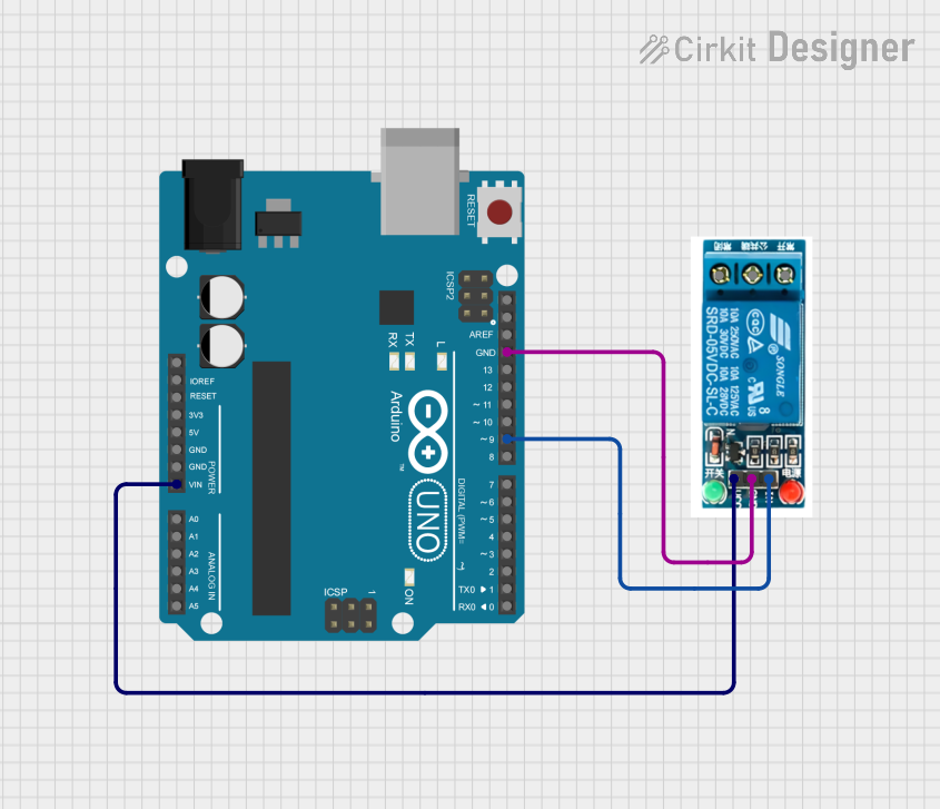
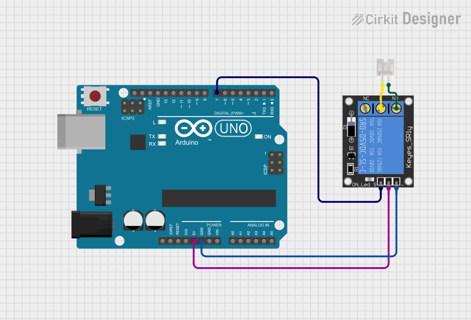
Example: Controlling a Relay with an Arduino UNO
Below is an example of how to control the relay using an Arduino UNO:
// Define the pin connected to the relay's coil (pin 86)
const int relayPin = 7;

void setup() {
  // Set the relay pin as an output
  pinMode(relayPin, OUTPUT);
}

void loop() {
  // Activate the relay (connects pin 30 to pin 87)
  digitalWrite(relayPin, HIGH);
  delay(5000); // Keep the relay on for 5 seconds

  // Deactivate the relay (connects pin 30 to pin 87a)
  digitalWrite(relayPin, LOW);
  delay(5000); // Keep the relay off for 5 seconds
}
Note: Use a transistor or relay driver circuit between the Arduino and the relay to handle the coil current safely.
Troubleshooting and FAQs
Common Issues and Solutions
Relay Not Activating:
- Cause: Insufficient control voltage or current.
- Solution: Verify that the control signal is 12V and capable of supplying ~150 mA. Use a transistor driver if necessary.
Load Not Powering On:
- Cause: Incorrect wiring of the load or power source.
- Solution: Double-check the connections to pins 30, 87, and 87a.
Relay Buzzing or Clicking Rapidly:
- Cause: Unstable control signal or insufficient power supply.
- Solution: Ensure the control signal is stable and the power supply can handle the relay's coil current.
Burnt Contacts:
- Cause: Load current exceeds the relay's contact rating.
- Solution: Use a relay with a higher current rating or reduce the load current.
FAQs
Q: Can I use this relay with a 5V control signal?
A: No, this relay is designed for a 12V control signal. Use a 5V relay or a transistor driver to step up the control voltage.
Q: What is the purpose of the NC (Normally Closed) terminal?
A: The NC terminal (pin 87a) is connected to the common terminal (pin 30) when the relay is not activated. It is used for applications where the load should be powered in the relay's default state.
Q: Can this relay handle AC loads?
A: While the relay can switch AC loads, it is primarily designed for DC automotive applications. Ensure the load voltage and current are within the relay's specifications.