Cirkit Designer
Your all-in-one circuit design IDE
Home /
Component Documentation
How to Use MOS FET Trigger Drive Switch: Examples, Pinouts, and Specs
Introduction
A MOSFET (Metal-Oxide-Semiconductor Field-Effect Transistor) is a type of transistor used for amplifying or switching electronic signals. The MOSFET Trigger Drive Switch is specifically designed to control the flow of electrical current in a circuit, often triggered by a small input voltage. This component is widely used in various applications, including power management, motor control, and signal switching.
Explore Projects Built with MOS FET Trigger Drive Switch
Pixhawk-Controlled Solenoid Driver with Voltage Regulation

This circuit uses an LM393 comparator to drive an IRFZ44N MOSFET based on the comparison between two input signals from a pixhawk 2.4.8 flight controller. The MOSFET switches a solenoid, with a diode for back EMF protection, and the system is powered by a Lipo battery with voltage regulation provided by a step-up boost converter and a step-down voltage regulator to ensure stable operation. A resistor is connected to the gate of the MOSFET for proper biasing.
STM32 Nucleo-Controlled Solenoid Actuation System

This circuit appears to be a microcontroller-driven array of push-pull solenoids with flyback diodes for protection. The STM32 Nucleo F303RE microcontroller's GPIO pins are connected to the gates of several nMOS transistors, which act as switches to control the current flow to the solenoids. A pushbutton with a pull-up resistor is also interfaced with the microcontroller for user input, and the power supply is connected to the solenoids with ground return paths through the nMOS transistors.
Arduino Controlled Solenoid Activation with MOSFET Switching
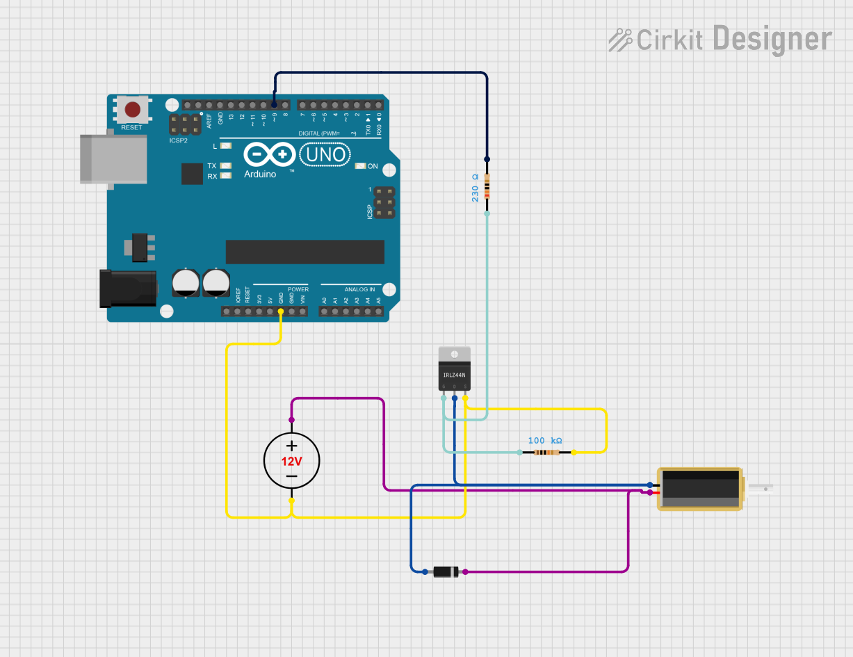
This circuit utilizes an Arduino UNO to control a solenoid via a MOSFET switch, powered by a 12V DC power supply. The Arduino activates the MOSFET gate through pin D9, allowing the solenoid to be turned on and off in one-second intervals, effectively controlling its operation.
Dual Motor Control Circuit with LED Indicator and Adjustable Speed

This circuit is designed to control the speed and direction of coreless motors using MOSFETs, with a potentiometer providing adjustable speed control for one direction. A rocker switch enables power control, and a red LED serves as a power indicator. Diodes are included for motor back-EMF protection.
Explore Projects Built with MOS FET Trigger Drive Switch
Pixhawk-Controlled Solenoid Driver with Voltage Regulation
This circuit uses an LM393 comparator to drive an IRFZ44N MOSFET based on the comparison between two input signals from a pixhawk 2.4.8 flight controller. The MOSFET switches a solenoid, with a diode for back EMF protection, and the system is powered by a Lipo battery with voltage regulation provided by a step-up boost converter and a step-down voltage regulator to ensure stable operation. A resistor is connected to the gate of the MOSFET for proper biasing.
STM32 Nucleo-Controlled Solenoid Actuation System
This circuit appears to be a microcontroller-driven array of push-pull solenoids with flyback diodes for protection. The STM32 Nucleo F303RE microcontroller's GPIO pins are connected to the gates of several nMOS transistors, which act as switches to control the current flow to the solenoids. A pushbutton with a pull-up resistor is also interfaced with the microcontroller for user input, and the power supply is connected to the solenoids with ground return paths through the nMOS transistors.
Arduino Controlled Solenoid Activation with MOSFET Switching
This circuit utilizes an Arduino UNO to control a solenoid via a MOSFET switch, powered by a 12V DC power supply. The Arduino activates the MOSFET gate through pin D9, allowing the solenoid to be turned on and off in one-second intervals, effectively controlling its operation.
Dual Motor Control Circuit with LED Indicator and Adjustable Speed
This circuit is designed to control the speed and direction of coreless motors using MOSFETs, with a potentiometer providing adjustable speed control for one direction. A rocker switch enables power control, and a red LED serves as a power indicator. Diodes are included for motor back-EMF protection.
Common Applications and Use Cases
- Power Management: Efficiently switching power to different parts of a circuit.
- Motor Control: Controlling the speed and direction of motors in robotics and automation.
- Signal Switching: Switching signals in communication devices and other electronic systems.
- LED Drivers: Controlling the brightness of LEDs in lighting applications.
Technical Specifications
Key Technical Details
| Parameter | Value |
|---|---|
| Drain-Source Voltage (VDS) | 60V |
| Gate-Source Voltage (VGS) | ±20V |
| Continuous Drain Current (ID) | 30A |
| Power Dissipation (PD) | 150W |
| RDS(on) (Max) | 0.02Ω |
| Threshold Voltage (VGS(th)) | 2-4V |
| Operating Temperature Range | -55°C to 150°C |
Pin Configuration and Descriptions
| Pin Number | Pin Name | Description |
|---|---|---|
| 1 | Gate | Controls the MOSFET switching |
| 2 | Drain | Current flows from drain to source |
| 3 | Source | Current flows to ground or load |
Usage Instructions
How to Use the Component in a Circuit
- Identify the Pins: Ensure you correctly identify the Gate, Drain, and Source pins.
- Connect the Gate: Connect the Gate pin to the control signal, which can be from a microcontroller like an Arduino.
- Connect the Drain: Connect the Drain pin to the load you want to control.
- Connect the Source: Connect the Source pin to the ground or the negative terminal of the power supply.
Important Considerations and Best Practices
- Gate Resistor: Use a gate resistor (typically 10-100Ω) to limit the inrush current and protect the microcontroller.
- Heat Dissipation: Ensure proper heat dissipation using a heatsink if the MOSFET is handling high currents.
- Flyback Diode: When controlling inductive loads like motors, use a flyback diode to protect the MOSFET from voltage spikes.
Example Circuit with Arduino UNO
// Example code to control a MOSFET with an Arduino UNO
const int gatePin = 9; // Pin connected to the Gate of the MOSFET

void setup() {
  pinMode(gatePin, OUTPUT); // Set the gate pin as an output
}

void loop() {
  digitalWrite(gatePin, HIGH); // Turn on the MOSFET
  delay(1000); // Wait for 1 second
  digitalWrite(gatePin, LOW); // Turn off the MOSFET
  delay(1000); // Wait for 1 second
}
Troubleshooting and FAQs
Common Issues Users Might Face
MOSFET Not Switching:
- Solution: Ensure the Gate voltage is sufficient to turn on the MOSFET. Check the threshold voltage (VGS(th)).
Overheating:
- Solution: Use a heatsink and ensure proper ventilation. Check the current rating and power dissipation.
Inconsistent Switching:
- Solution: Use a gate resistor to limit inrush current. Ensure the control signal is stable.
Solutions and Tips for Troubleshooting
- Check Connections: Verify all connections are secure and correctly placed.
- Measure Voltages: Use a multimeter to measure the Gate, Drain, and Source voltages.
- Use Proper Components: Ensure you are using components like resistors and diodes as recommended.
By following this documentation, users can effectively utilize the MOSFET Trigger Drive Switch in their electronic projects, ensuring efficient and reliable performance.