How to Use Mini AC-DC 110V-230V to 5V 700mA Module: Examples, Pinouts, and Specs
Introduction
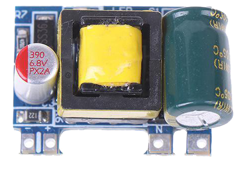
The Mini AC-DC 110V-230V to 5V 700mA Converter Module by PermanentFly is a compact power supply module that converts high-voltage AC power to a low-voltage 5V DC output. This module is ideal for powering 5V DC electronics from a standard AC power supply and is commonly used in DIY projects, IoT devices, and small household electronics.
Explore Projects Built with Mini AC-DC 110V-230V to 5V 700mA Module

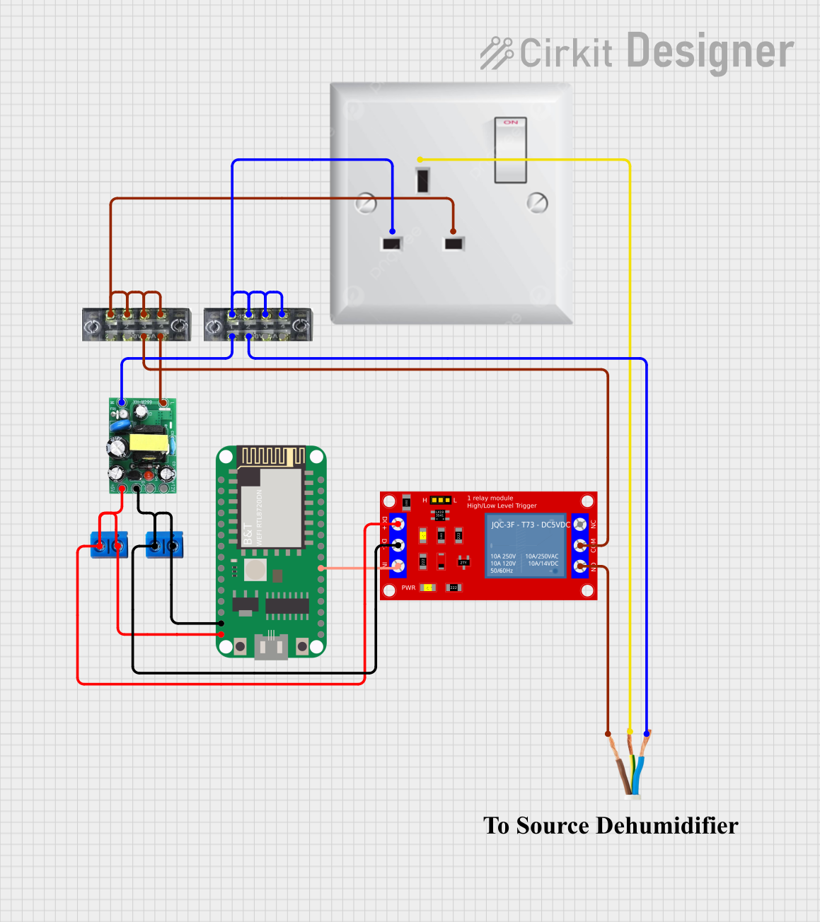

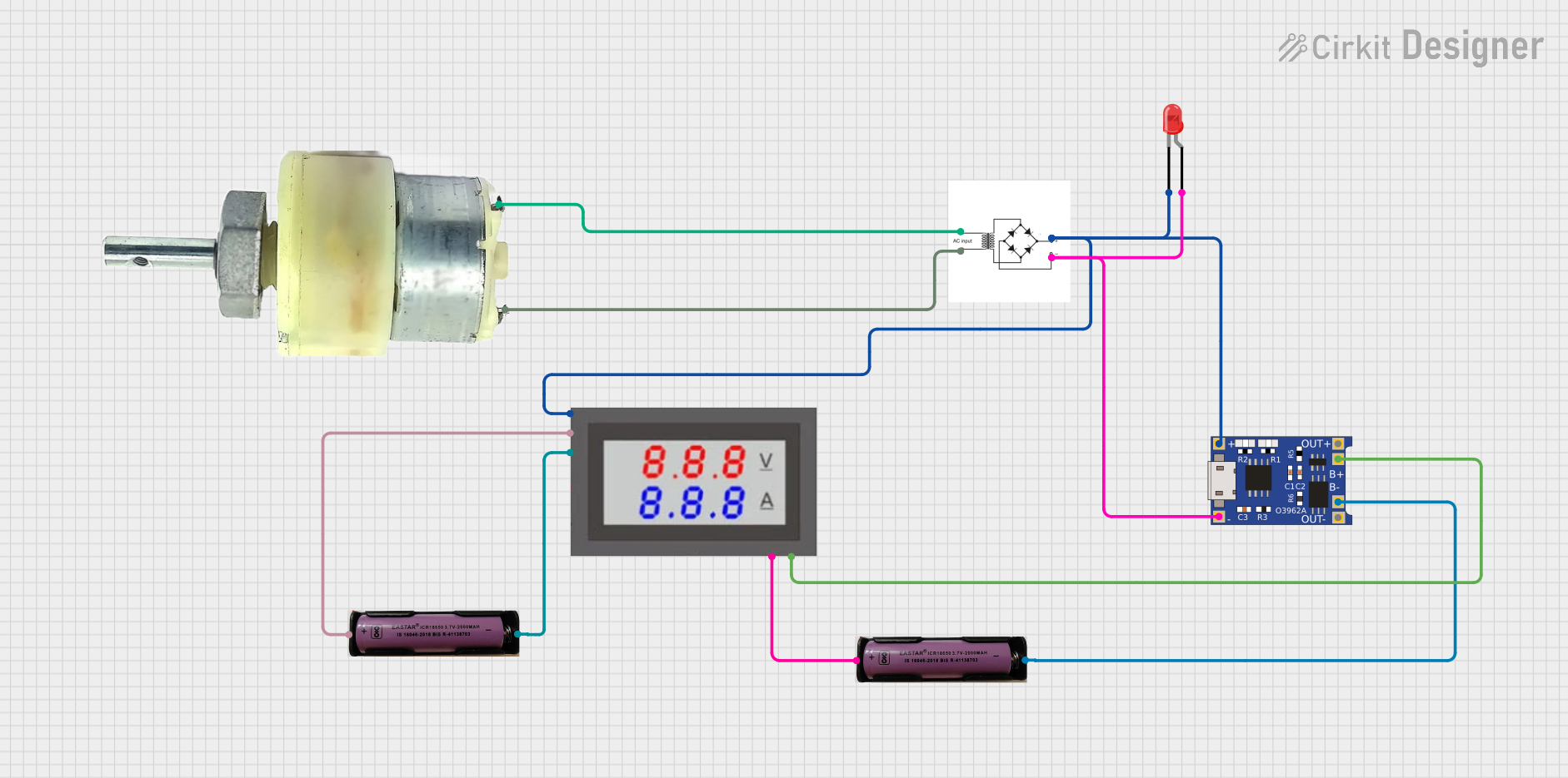
Explore Projects Built with Mini AC-DC 110V-230V to 5V 700mA Module
Common Applications and Use Cases
- Powering microcontrollers like Arduino or Raspberry Pi
- Supplying power to LED lighting systems
- Operating low-power sensors and modules in home automation
- Providing 5V DC to USB-powered devices
Technical Specifications
Key Technical Details
- Input Voltage: 110V-230V AC
- Output Voltage: 5V DC
- Maximum Output Current: 700mA
- Isolation Voltage: >1000V
- Operating Temperature: -20°C to 60°C
- Efficiency: >70%
Pin Configuration and Descriptions
| Pin Number | Description | Notes |
|---|---|---|
| 1 | AC Input (L) | Connect to live wire of AC input |
| 2 | AC Input (N) | Connect to neutral wire of AC input |
| 3 | DC Output (+5V) | Positive output terminal |
| 4 | DC Output (GND) | Ground output terminal |
Usage Instructions
How to Use the Component in a Circuit
AC Input Connection:
- Connect the live wire (L) from the AC mains to pin 1.
- Connect the neutral wire (N) from the AC mains to pin 2.
DC Output Connection:
- Connect the positive terminal of your device to pin 3 for the 5V output.
- Connect the ground terminal of your device to pin 4.
Important Considerations and Best Practices
- Ensure the module is properly insulated to prevent electrical shock.
- Verify the input voltage range before connecting to the AC mains.
- Do not exceed the maximum output current of 700mA.
- Use a fuse on the AC input for additional safety.
- Avoid placing the module in high-temperature environments.
- Double-check wiring to prevent short circuits or incorrect connections.
Troubleshooting and FAQs
Common Issues Users Might Face
- Insufficient Output Current: Ensure that the total current draw of the connected devices does not exceed 700mA.
- Overheating: If the module is overheating, check if the current draw is within limits and provide adequate ventilation.
- No Output Voltage: Check AC input connections and ensure the module is not damaged.
Solutions and Tips for Troubleshooting
- Always start by checking the connections and ensuring that the input voltage is within the specified range.
- If the output voltage is unstable or there is no output, inspect the module for any signs of physical damage.
- Use a multimeter to verify the output voltage and current to ensure they are within specifications.
FAQs
Q: Can I use this module to power a USB device? A: Yes, as long as the device operates at 5V and requires less than 700mA.
Q: Is this module isolated? A: Yes, it has an isolation voltage of over 1000V, but always handle with care.
Q: Can I connect multiple devices to this module? A: Yes, multiple devices can be connected as long as their combined current draw does not exceed 700mA.
Example Code for Arduino UNO
// This example demonstrates how to power an Arduino UNO using the Mini AC-DC Converter Module.

void setup() {
  // Initialize the digital pin as an output.
  pinMode(LED_BUILTIN, OUTPUT); // Most Arduinos have an on-board LED on pin 13
}

void loop() {
  digitalWrite(LED_BUILTIN, HIGH);   // Turn the LED on
  delay(1000);                       // Wait for a second
  digitalWrite(LED_BUILTIN, LOW);    // Turn the LED off
  delay(1000);                       // Wait for a second
}

// Note: The above code does not interact with the power module directly.
// It assumes that the Arduino is being powered by the 5V output from the module.
Remember to follow all safety precautions when working with AC mains power. This documentation is provided for informational purposes only, and it is the user's responsibility to ensure safe and proper use of the equipment.