How to Use DIN 5 Pin: Examples, Pinouts, and Specs
Introduction
The DIN 5 Pin connector is a circular, 5-pin connector widely used in audio and MIDI (Musical Instrument Digital Interface) devices. It is designed to transmit multiple signals simultaneously, making it ideal for applications requiring compact and reliable connections. The connector is commonly found in musical instruments, audio equipment, and legacy computer systems.
Explore Projects Built with DIN 5 Pin


Explore Projects Built with DIN 5 Pin
Common Applications and Use Cases
- MIDI communication between musical instruments and controllers
- Audio signal transmission in vintage audio equipment
- Data transfer in legacy computer systems
- Power and signal connections in industrial equipment
Technical Specifications
Key Technical Details
- Number of Pins: 5
- Connector Type: Circular DIN
- Pin Spacing: 1.27 mm (standard DIN spacing)
- Voltage Rating: Typically up to 24V (varies by application)
- Current Rating: Typically up to 1A per pin
- Material: Metal shell with plastic insulation
- Mounting Style: Panel mount or cable mount
- Durability: Rated for thousands of mating cycles
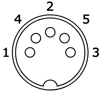
Pin Configuration and Descriptions
The DIN 5 Pin connector has five pins arranged in a 180-degree arc. Below is the pinout configuration:
| Pin Number | Description | Common Use |
|---|---|---|
| 1 | Signal/Data Line 1 | MIDI Out or Audio Signal |
| 2 | Ground | Common Ground |
| 3 | Signal/Data Line 2 | MIDI In or Audio Signal |
| 4 | Signal/Data Line 3 | Auxiliary Signal or Power |
| 5 | Signal/Data Line 4 | Auxiliary Signal or Power |
Note: The specific function of each pin may vary depending on the application. Always refer to the device's datasheet or manual for exact pin assignments.
Usage Instructions
How to Use the DIN 5 Pin in a Circuit
- Identify the Pinout: Refer to the pin configuration table above to understand the function of each pin.
- Soldering: If using a cable-mount connector, solder the wires to the appropriate pins. Ensure proper insulation to avoid short circuits.
- Panel Mounting: For panel-mount connectors, secure the connector to the panel using screws or a locking mechanism.
- Connection: Plug the male connector into the female socket, ensuring proper alignment to avoid damaging the pins.
- Testing: Verify the connections using a multimeter to ensure continuity and correct wiring.
Important Considerations and Best Practices
- Polarity: Double-check the polarity of power and signal lines to prevent damage to connected devices.
- Shielding: Use shielded cables to minimize interference, especially in audio and MIDI applications.
- Alignment: Ensure proper alignment when connecting to avoid bending or breaking the pins.
- Current and Voltage Ratings: Do not exceed the specified current and voltage ratings to maintain safe operation.
Example: Connecting a DIN 5 Pin to an Arduino UNO for MIDI Communication
The DIN 5 Pin connector is commonly used for MIDI communication. Below is an example of how to connect it to an Arduino UNO:
Circuit Diagram
- Pin 2 (Ground): Connect to Arduino GND.
- Pin 4 (MIDI Data): Connect to Arduino TX (Digital Pin 1) through a 220-ohm resistor.
- Pin 5 (MIDI Data): Connect to a 5V power source through a 220-ohm resistor.
Arduino Code
// MIDI Communication Example with Arduino UNO
// This code sends a MIDI note-on message to a connected MIDI device.

void setup() {
  Serial.begin(31250); // MIDI communication baud rate
}

void loop() {
  // Send a MIDI Note On message (Channel 1, Note 60, Velocity 100)
  sendMIDI(0x90, 60, 100);
  delay(500); // Wait for 500ms
  // Send a MIDI Note Off message (Channel 1, Note 60, Velocity 0)
  sendMIDI(0x80, 60, 0);
  delay(500); // Wait for 500ms
}

void sendMIDI(byte command, byte data1, byte data2) {
  Serial.write(command); // Send MIDI command byte
  Serial.write(data1);   // Send first data byte (e.g., note number)
  Serial.write(data2);   // Send second data byte (e.g., velocity)
}
Note: Use a 5-pin DIN MIDI breakout board or a custom circuit to interface the DIN connector with the Arduino.
Troubleshooting and FAQs
Common Issues and Solutions
Problem: No signal or data transmission.
- Solution: Check the wiring and ensure all connections are secure. Verify the pinout and polarity.
Problem: Interference or noise in the signal.
- Solution: Use shielded cables and ensure proper grounding.
Problem: Bent or broken pins.
- Solution: Handle the connector carefully and ensure proper alignment during connection.
Problem: Arduino not communicating with the MIDI device.
- Solution: Verify the baud rate (31250 for MIDI) and check the circuit for correct resistor values.
FAQs
Q: Can I use the DIN 5 Pin connector for power transmission?
A: Yes, but ensure the current and voltage do not exceed the connector's ratings.Q: Is the DIN 5 Pin compatible with modern MIDI devices?
A: Yes, it is the standard connector for MIDI communication.Q: Can I use the DIN 5 Pin for audio signals?
A: Yes, it is commonly used in vintage audio equipment for stereo or mono audio signals.Q: How do I clean the connector?
A: Use a soft brush or compressed air to remove dust. Avoid using liquids that may damage the pins.
This documentation provides a comprehensive guide to understanding and using the DIN 5 Pin connector effectively.