How to Use 7490 IC Decade Counter DIP-14: Examples, Pinouts, and Specs
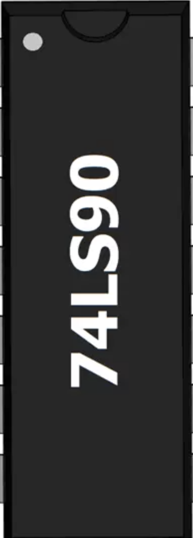
7490 IC Decade Counter (DIP-14) Documentation
1. Introduction
The 7490 IC is a 4-bit binary decade counter designed to count from 0 to 9 in binary format. It is widely used in digital electronics for counting applications, such as frequency division, digital clocks, event counters, and more. The IC is housed in a DIP-14 (Dual Inline Package), making it easy to integrate into breadboards and circuit boards.
The 7490 IC is a versatile component that can be configured as a divide-by-2, divide-by-5, or divide-by-10 counter, depending on the circuit design. Its robust design and ease of use make it a popular choice for both beginners and experienced engineers.
Common Applications
- Digital clocks and timers
- Frequency counters
- Event counters
- Frequency division circuits
- LED-based numerical displays
2. Technical Specifications
The following table outlines the key technical specifications of the 7490 IC:
| Parameter | Value |
|---|---|
| Supply Voltage (Vcc) | 4.5V to 5.5V (Typical: 5V) |
| Input Voltage (High) | 2V (Minimum) |
| Input Voltage (Low) | 0.8V (Maximum) |
| Output Voltage (High) | 2.4V (Minimum) |
| Output Voltage (Low) | 0.4V (Maximum) |
| Maximum Clock Frequency | 42 MHz |
| Power Dissipation | 500 mW (Maximum) |
| Operating Temperature | 0°C to 70°C |
| Package Type | DIP-14 |
Pin Configuration and Descriptions
The 7490 IC has 14 pins, as shown in the table below:
| Pin Number | Pin Name | Description |
|---|---|---|
| 1 | Vcc | Positive power supply (4.5V to 5.5V). |
| 2 | QD | Output for the 4th flip-flop (MSB of the counter). |
| 3 | QC | Output for the 3rd flip-flop. |
| 4 | QB | Output for the 2nd flip-flop. |
| 5 | QA | Output for the 1st flip-flop (LSB of the counter). |
| 6 | Clock B | Input for the divide-by-5 counter. |
| 7 | GND | Ground (0V). |
| 8 | Clock A | Input for the divide-by-2 counter. |
| 9 | Reset | Resets the counter to 0 when HIGH. |
| 10 | Set | Sets the counter to 9 when HIGH. |
| 11 | NC | No connection. |
| 12 | NC | No connection. |
| 13 | NC | No connection. |
| 14 | Carry Out | Output for cascading multiple counters. |
3. Usage Instructions
Basic Circuit Configuration
To use the 7490 IC as a decade counter, follow these steps:
- Power Supply: Connect pin 1 (Vcc) to a 5V power supply and pin 7 (GND) to ground.
- Clock Input: Provide a clock signal to pin 8 (Clock A). This signal determines the counting speed.
- Outputs: Connect pins 2 (QD), 3 (QC), 4 (QB), and 5 (QA) to LEDs or other display devices to observe the binary count.
- Reset and Set: Leave pins 9 (Reset) and 10 (Set) unconnected for normal operation. If needed, connect them to control signals to reset or set the counter.
Important Considerations
- Use a debounced clock signal to avoid erratic counting due to noise.
- Ensure the supply voltage is within the specified range (4.5V to 5.5V).
- Avoid leaving unused inputs floating; connect them to GND or Vcc as needed.
- For cascading multiple 7490 ICs, use the Carry Out (pin 14) to drive the clock input of the next IC.
4. Example Circuit with Arduino UNO
The 7490 IC can be easily interfaced with an Arduino UNO to create a simple counter. Below is an example circuit and code:
Circuit Connections
- Connect pin 1 (Vcc) to the Arduino's 5V pin and pin 7 (GND) to the Arduino's GND.
- Connect pin 8 (Clock A) to Arduino digital pin 2.
- Connect pins 2 (QD), 3 (QC), 4 (QB), and 5 (QA) to LEDs with current-limiting resistors (220Ω) to observe the binary count.
- Leave pins 9 (Reset) and 10 (Set) unconnected for normal operation.
Arduino Code
// 7490 Decade Counter Example with Arduino UNO
// This code generates a clock signal on pin 2 to drive the 7490 IC.

const int clockPin = 2; // Pin connected to Clock A (pin 8 of 7490)
const int delayTime = 500; // Delay time in milliseconds (adjust for speed)

void setup() {
  pinMode(clockPin, OUTPUT); // Set clock pin as output
}

void loop() {
  digitalWrite(clockPin, HIGH); // Generate HIGH signal
  delay(delayTime);            // Wait for half the clock period
  digitalWrite(clockPin, LOW); // Generate LOW signal
  delay(delayTime);            // Wait for half the clock period
}
Explanation
- The Arduino generates a square wave on pin 2, which acts as the clock signal for the 7490 IC.
- The LEDs connected to the output pins (QA, QB, QC, QD) will display the binary count from 0 to 9.
5. Troubleshooting and FAQs
Common Issues and Solutions
| Issue | Possible Cause | Solution |
|---|---|---|
| Counter does not increment. | No clock signal or incorrect connections. | Verify the clock signal and ensure proper wiring of the IC. |
| Erratic counting or skipping numbers. | Noisy clock signal or floating inputs. | Use a debounced clock signal and connect unused inputs to GND or Vcc. |
| Outputs do not light up. | LEDs not connected properly or damaged. | Check LED connections and replace damaged LEDs. |
| Counter resets unexpectedly. | Noise on Reset or Set pins. | Pull Reset and Set pins LOW using pull-down resistors if not in use. |
FAQs
Can I cascade multiple 7490 ICs for higher counts?
- Yes, use the Carry Out (pin 14) of one IC to drive the clock input of the next IC.
What is the maximum clock frequency for the 7490 IC?
- The maximum clock frequency is 42 MHz, but ensure your circuit design can handle high-speed signals.
Can I use the 7490 IC with a 3.3V power supply?
- No, the 7490 IC requires a minimum supply voltage of 4.5V. Use a 5V power supply for proper operation.
How do I reset the counter to 0?
- Apply a HIGH signal to the Reset (pin 9) to reset the counter to 0.
This documentation provides a comprehensive guide to using the 7490 IC Decade Counter. Whether you're building a digital clock or experimenting with counters, the 7490 IC is a reliable and versatile choice.
Explore Projects Built with 7490 IC Decade Counter DIP-14

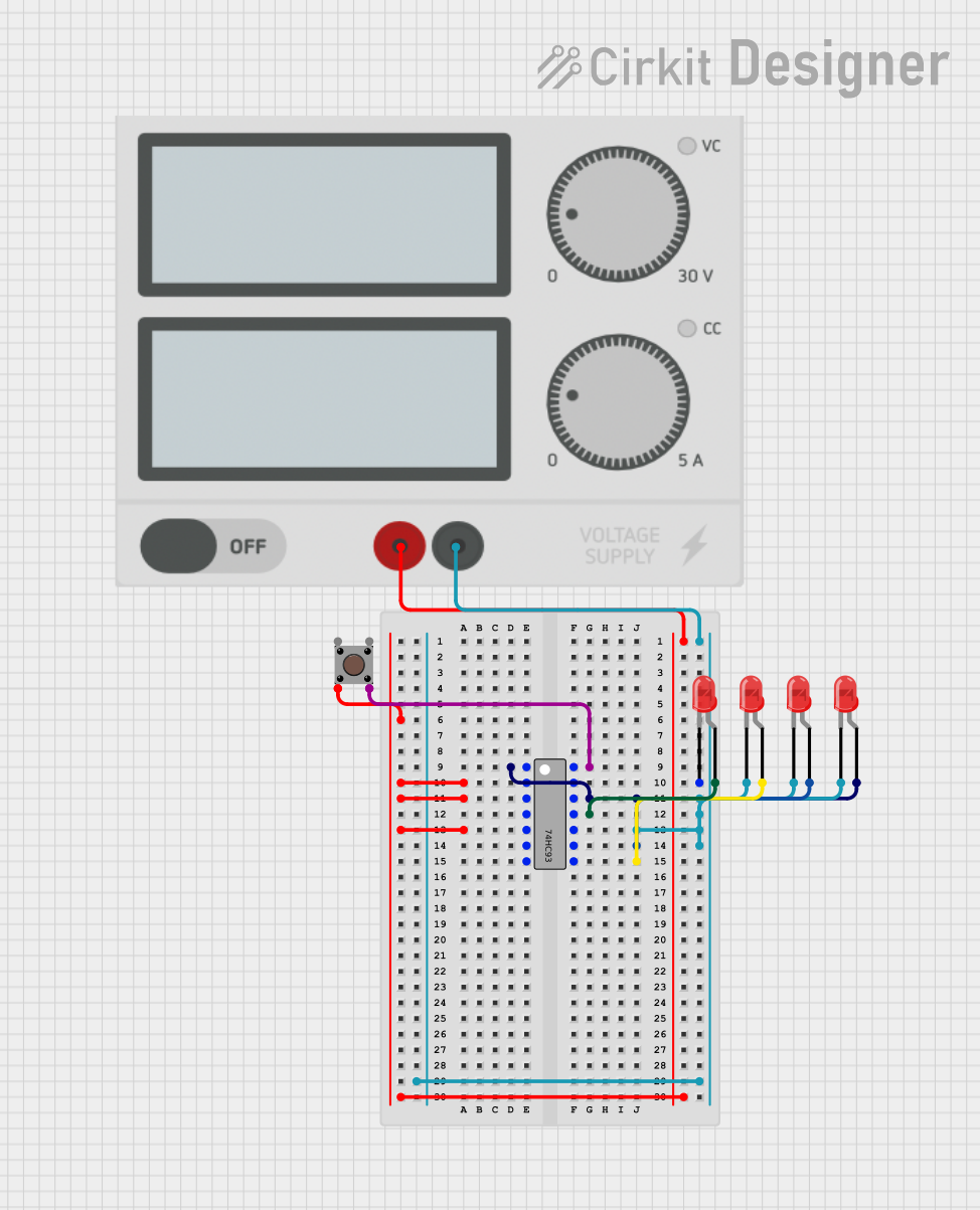
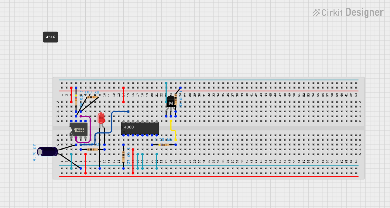
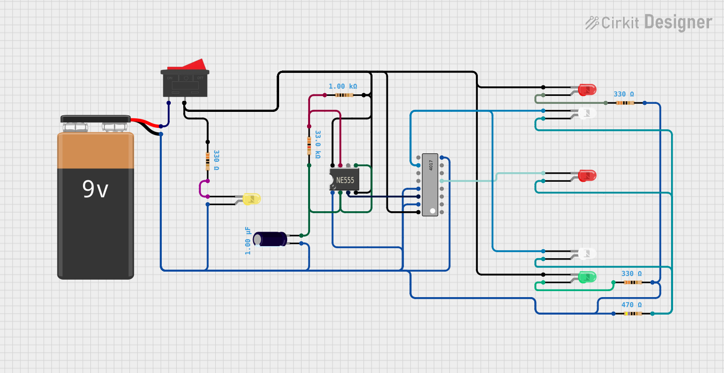
Explore Projects Built with 7490 IC Decade Counter DIP-14