Cirkit Designer Logo
Cirkit Designer
Your all-in-one circuit design IDE
Home / 
Component Documentation

How to Use TA6568: Examples, Pinouts, and Specs

Image of TA6568
Cirkit Designer LogoDesign with TA6568 in Cirkit Designer

Introduction

The TA6568 is a dual operational amplifier (op-amp) designed for audio amplification and signal conditioning applications. It is characterized by its high input impedance and low output impedance, which makes it an excellent choice for interfacing with high-impedance sources and driving low-impedance loads, such as headphones or speakers. The TA6568 is commonly used in pre-amplifiers, active filters, and audio mixers.

Explore Projects Built with TA6568

Use Cirkit Designer to design, explore, and prototype these projects online. Some projects support real-time simulation. Click "Open Project" to start designing instantly!
Pushbutton-Controlled Dual-Color LED Circuit with TA6568
Image of polarity detector: A project utilizing TA6568 in a practical application
This is a pushbutton-controlled LED circuit with a TA6568 chip that likely drives two LEDs (red and green). Each LED is connected to a pushbutton through the TA6568, allowing the user to toggle the state of the LEDs. The circuit is powered by a 3V battery and includes a JST connector for external interfacing.
Cirkit Designer LogoOpen Project in Cirkit Designer
Arduino Nano Based GPS Tracker with GSM Communication and Accelerometer
Image of Circuit Aayush: A project utilizing TA6568 in a practical application
This circuit is designed for communication and location tracking purposes. It features an Arduino Nano interfaced with a SIM800L GSM module for cellular connectivity, a GPS NEO 6M module for obtaining geographical coordinates, and an AITrip ADXL335 GY-61 accelerometer for motion sensing. The LM2596 Step Down Module is used to regulate the power supply to the components.
Cirkit Designer LogoOpen Project in Cirkit Designer
Satellite-Based Timing and Navigation System with SDR and Atomic Clock Synchronization
Image of GPS 시스템 측정 구성도_Confirm: A project utilizing TA6568 in a practical application
This circuit appears to be a complex system involving power supply management, GPS and timing synchronization, and data communication. It includes a SI-TEX G1 Satellite Compass for GPS data, an XHTF1021 Atomic Rubidium Clock for precise timing, and Ettus USRP B200 units for software-defined radio communication. Power is supplied through various SMPS units and distributed via terminal blocks and DC jacks. Data communication is facilitated by Beelink MINI S12 N95 computers, RS232 splitters, and a 1000BASE-T Media Converter for network connectivity. RF Directional Couplers are used to interface antennas with the USRP units, and the entire system is likely contained within cases for protection and organization.
Cirkit Designer LogoOpen Project in Cirkit Designer
Battery-Powered Raspberry Pi Pico GPS Tracker with Sensor Integration
Image of Copy of CanSet v1: A project utilizing TA6568 in a practical application
This circuit is a data acquisition and communication system powered by a LiPoly battery and managed by a Raspberry Pi Pico. It includes sensors (BMP280, MPU9250) for environmental data, a GPS module for location tracking, an SD card for data storage, and a WLR089-CanSAT for wireless communication. The TP4056 module handles battery charging, and a toggle switch controls power distribution.
Cirkit Designer LogoOpen Project in Cirkit Designer

Explore Projects Built with TA6568

Use Cirkit Designer to design, explore, and prototype these projects online. Some projects support real-time simulation. Click "Open Project" to start designing instantly!
Image of polarity detector: A project utilizing TA6568 in a practical application
Pushbutton-Controlled Dual-Color LED Circuit with TA6568
This is a pushbutton-controlled LED circuit with a TA6568 chip that likely drives two LEDs (red and green). Each LED is connected to a pushbutton through the TA6568, allowing the user to toggle the state of the LEDs. The circuit is powered by a 3V battery and includes a JST connector for external interfacing.
Cirkit Designer LogoOpen Project in Cirkit Designer
Image of Circuit Aayush: A project utilizing TA6568 in a practical application
Arduino Nano Based GPS Tracker with GSM Communication and Accelerometer
This circuit is designed for communication and location tracking purposes. It features an Arduino Nano interfaced with a SIM800L GSM module for cellular connectivity, a GPS NEO 6M module for obtaining geographical coordinates, and an AITrip ADXL335 GY-61 accelerometer for motion sensing. The LM2596 Step Down Module is used to regulate the power supply to the components.
Cirkit Designer LogoOpen Project in Cirkit Designer
Image of GPS 시스템 측정 구성도_Confirm: A project utilizing TA6568 in a practical application
Satellite-Based Timing and Navigation System with SDR and Atomic Clock Synchronization
This circuit appears to be a complex system involving power supply management, GPS and timing synchronization, and data communication. It includes a SI-TEX G1 Satellite Compass for GPS data, an XHTF1021 Atomic Rubidium Clock for precise timing, and Ettus USRP B200 units for software-defined radio communication. Power is supplied through various SMPS units and distributed via terminal blocks and DC jacks. Data communication is facilitated by Beelink MINI S12 N95 computers, RS232 splitters, and a 1000BASE-T Media Converter for network connectivity. RF Directional Couplers are used to interface antennas with the USRP units, and the entire system is likely contained within cases for protection and organization.
Cirkit Designer LogoOpen Project in Cirkit Designer
Image of Copy of CanSet v1: A project utilizing TA6568 in a practical application
Battery-Powered Raspberry Pi Pico GPS Tracker with Sensor Integration
This circuit is a data acquisition and communication system powered by a LiPoly battery and managed by a Raspberry Pi Pico. It includes sensors (BMP280, MPU9250) for environmental data, a GPS module for location tracking, an SD card for data storage, and a WLR089-CanSAT for wireless communication. The TP4056 module handles battery charging, and a toggle switch controls power distribution.
Cirkit Designer LogoOpen Project in Cirkit Designer

Technical Specifications

General Characteristics

  • Supply Voltage (VCC): ±3V to ±15V
  • Input Offset Voltage: 3mV (max)
  • Input Bias Current: 500nA (max)
  • Slew Rate: 1V/µs (typ)
  • Gain Bandwidth Product: 10MHz (typ)

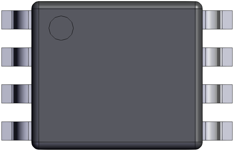
Pin Configuration and Descriptions

Pin Number Name Description
1 OUT1 Output of Amplifier 1
2 IN1- Inverting input of Amplifier 1
3 IN1+ Non-inverting input of Amplifier 1
4 VEE Negative supply voltage
5 IN2+ Non-inverting input of Amplifier 2
6 IN2- Inverting input of Amplifier 2
7 OUT2 Output of Amplifier 2
8 VCC Positive supply voltage

Usage Instructions

Basic Connection

To use the TA6568 in a circuit, connect the power supply to pins 4 (VEE) and 8 (VCC), ensuring that the supply voltage does not exceed the specified limits. Connect the input signal to the non-inverting input (IN1+ or IN2+) for a non-inverted output, or to the inverting input (IN1- or IN2-) for an inverted output. The output can be taken from OUT1 or OUT2.

Best Practices

  • Use bypass capacitors close to the power supply pins to minimize noise.
  • Keep signal paths short to reduce interference.
  • Ensure proper grounding to avoid ground loops.
  • Use feedback resistors to set the desired gain for the amplifier.

Example Circuit: Audio Amplifier with Arduino UNO

// Code to control volume of audio signal using Arduino UNO and TA6568

const int analogInPin = A0; // Analog input pin for potentiometer
const int analogOutPin = 9; // PWM output pin connected to TA6568 volume control

int sensorValue = 0;        // Value read from the potentiometer
int outputValue = 0;        // Value output to the PWM (analog out)

void setup() {
  // Initialize serial communication at 9600 bits per second:
  Serial.begin(9600);
}

void loop() {
  // Read the potentiometer value
  sensorValue = analogRead(analogInPin);
  // Map it to the range of the analog out (PWM):
  outputValue = map(sensorValue, 0, 1023, 0, 255);
  // Change the analog out value:
  analogWrite(analogOutPin, outputValue);

  // Print the results to the serial monitor:
  Serial.print("sensor = ");
  Serial.print(sensorValue);
  Serial.print("\t output = ");
  Serial.println(outputValue);

  // Wait 2 milliseconds before the next loop
  // for the analog-to-digital converter to settle
  // after the last reading:
  delay(2);
}

Troubleshooting and FAQs

Common Issues

  • No Output: Ensure that the power supply is connected correctly and within the specified voltage range. Check for proper input signal connection.
  • Distorted Sound: This could be due to overdriving the input or output. Check the input signal level and ensure the output is not exceeding the amplifier's capabilities.
  • Hum or Noise: Ensure that the power supply is clean and that bypass capacitors are used. Check for proper grounding and avoid long signal paths.

FAQs

Q: Can the TA6568 be used with a single supply voltage? A: Yes, the TA6568 can be configured to operate with a single supply voltage, but a virtual ground at mid-supply level is typically needed.

Q: What is the maximum supply voltage for the TA6568? A: The maximum supply voltage is ±15V. Exceeding this voltage can damage the component.

Q: Can the TA6568 drive a speaker directly? A: While the TA6568 can drive low-impedance loads, it may not be powerful enough for all speakers. An additional power amplifier stage may be required for larger speakers.

Q: Is the TA6568 suitable for DC signal amplification? A: Yes, the TA6568 can be used for DC signal amplification, but care must be taken to manage offset voltages and drift.

This documentation provides a comprehensive overview of the TA6568 dual operational amplifier, ensuring users can effectively incorporate it into their audio applications.