How to Use Adafruit Latching Mini Relay FeatherWing: Examples, Pinouts, and Specs
Introduction
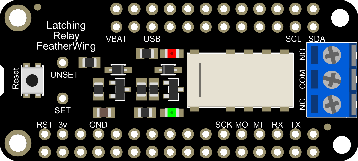
The Adafruit Latching Mini Relay FeatherWing is a compact, easy-to-use module designed to control high-current loads with a low-current digital signal. This relay module is particularly useful in applications where it is necessary to switch devices on and off without continuous power to the relay coil, as it maintains its state even when power is removed. Common applications include home automation, industrial controls, and IoT devices where power efficiency is crucial.
Explore Projects Built with Adafruit Latching Mini Relay FeatherWing


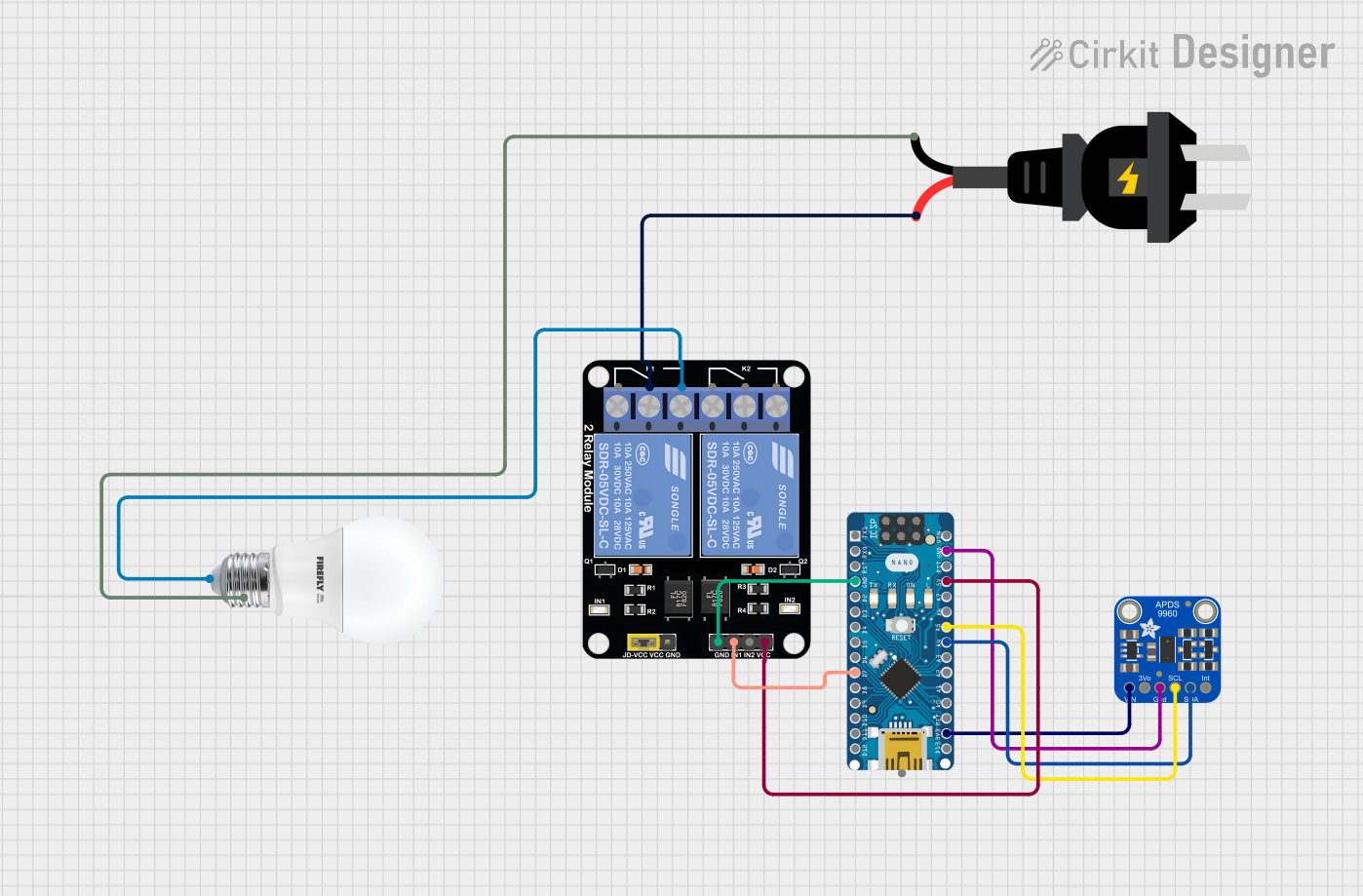
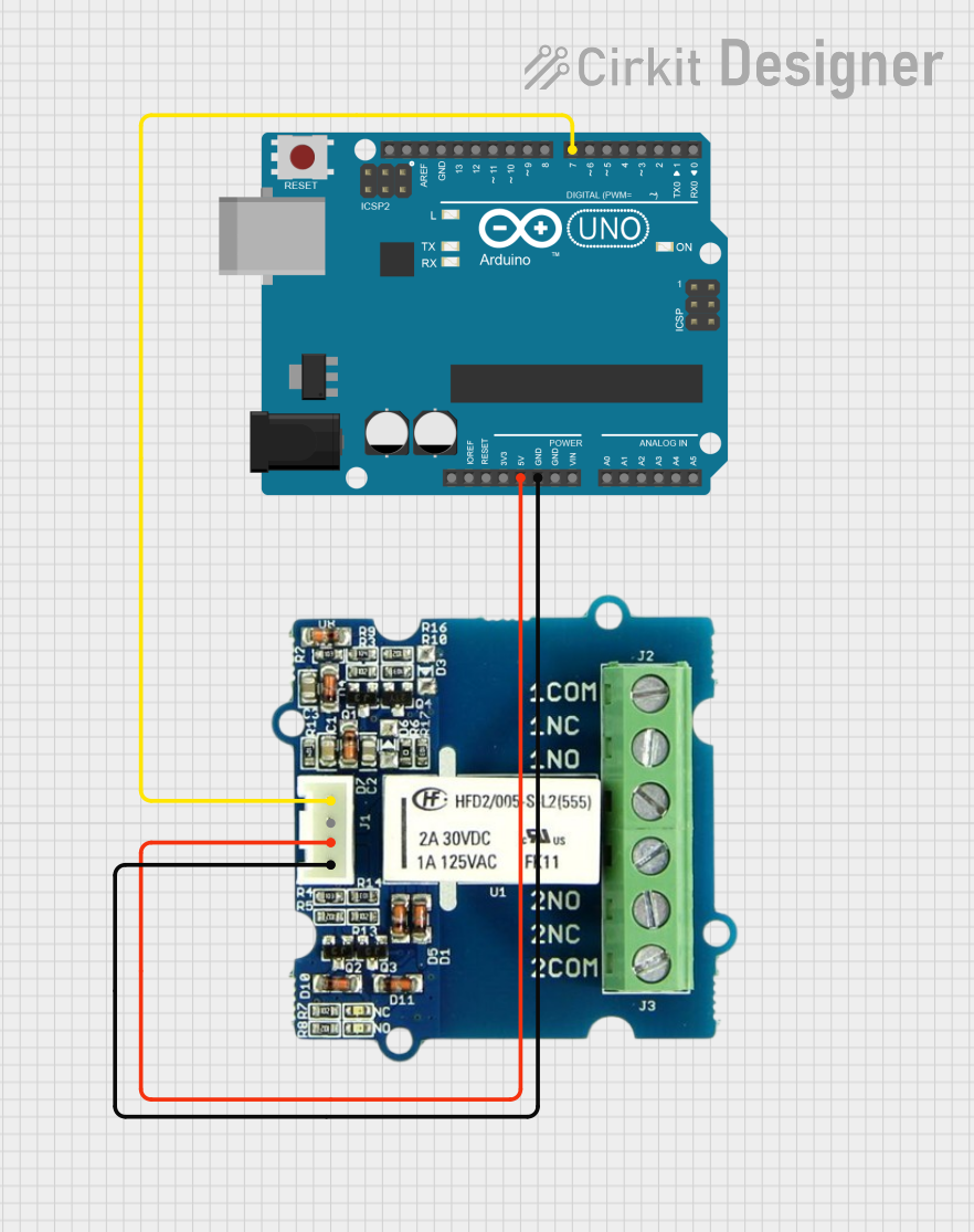
Explore Projects Built with Adafruit Latching Mini Relay FeatherWing
Technical Specifications
Key Technical Details
- Switching Voltage: Up to 60V DC or 125V AC
- Carrying Current: Up to 2A
- Coil Voltage: 3V DC
- Control Signal: 3-5V DC, compatible with 3.3V and 5V logic
- Dimensions: 22.9mm x 50.8mm x 7.6mm
- Weight: 4.5 grams
Pin Configuration and Descriptions
| Pin Name | Description |
|---|---|
| GND | Ground connection for the control circuit. |
| Signal | Digital input to control the relay (3-5V logic level). |
| +3V | Power supply for the relay coil (3V). |
| NC | Normally Closed contact - connected to Common when relay is not active. |
| NO | Normally Open contact - connected to Common when relay is active. |
| COM | Common contact - the common point for switching. |
Usage Instructions
How to Use the Component in a Circuit
- Power Connections: Connect the +3V pin to a 3V power supply and the GND pin to the ground of your power supply.
- Control Signal: Connect the Signal pin to a digital output pin on your microcontroller.
- Load Connections: Connect the device you wish to control to the NC or NO contacts, with the other side of the device connected to your power supply.
Important Considerations and Best Practices
- Ensure that the load does not exceed the rated switching voltage and carrying current of the relay.
- Use a flyback diode across inductive loads to prevent back EMF damage.
- Avoid placing high-power devices close to sensitive electronics to prevent interference.
- Always disconnect power before making or changing connections.
Example Code for Arduino UNO
// Pin connected to the relay control signal
const int relayPin = 2;

void setup() {
  // Set the relay control pin as an output
  pinMode(relayPin, OUTPUT);
  // Start with the relay in a known state (unlatched)
  digitalWrite(relayPin, LOW);
}

void loop() {
  // Latch the relay
  digitalWrite(relayPin, HIGH);
  delay(1000); // Wait for 1 second
  // Unlatch the relay
  digitalWrite(relayPin, LOW);
  delay(1000); // Wait for 1 second
}
Troubleshooting and FAQs
Common Issues
- Relay Does Not Switch: Ensure that the control signal is within the 3-5V range and that the power supply is properly connected to the +3V and GND pins.
- Intermittent Operation: Check for loose connections and ensure that the load does not exceed the relay's specifications.
- Unexpected Relay Behavior: Verify that the control signal is stable and not being affected by noise or voltage spikes.
Solutions and Tips for Troubleshooting
- Use a multimeter to check for continuity across the relay contacts in both states.
- Ensure that the power supply is capable of providing sufficient current for the relay coil.
- Implement debounce logic in the microcontroller code to prevent false triggering.
FAQs
Q: Can the relay be used with AC loads? A: Yes, the relay can switch AC loads up to 125V AC, but ensure the load does not exceed 2A.
Q: Is it necessary to power down the system to change the relay state? A: No, the latching feature allows the relay to maintain its state without continuous power, and it can be controlled by toggling the control signal.
Q: How do I know if the relay is in the latched or unlatched state? A: You can determine the state by checking the continuity between the COM and NO/NC contacts with a multimeter or by observing the behavior of the connected load.