How to Use lm2596: Examples, Pinouts, and Specs
Introduction
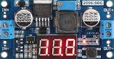
The LM2596 is a step-down (buck) voltage regulator designed to efficiently convert a higher input voltage into a stable, regulated output voltage. It is capable of delivering up to 3A of output current, making it ideal for powering a wide range of electronic devices. With its wide input voltage range (4.5V to 40V) and adjustable or fixed output voltage options, the LM2596 is a versatile component for power management in embedded systems, battery-powered devices, and industrial applications.
Explore Projects Built with lm2596


Explore Projects Built with lm2596
Common Applications and Use Cases
- Powering microcontrollers and sensors in embedded systems
- Battery charging circuits
- Voltage regulation in industrial equipment
- DC-DC converters for automotive applications
- Power supplies for LED drivers and communication devices
Technical Specifications
The LM2596 is available in both adjustable and fixed output voltage versions. Below are the key technical details:
General Specifications
| Parameter | Value |
|---|---|
| Input Voltage Range | 4.5V to 40V |
| Output Voltage Range | 1.23V to 37V (adjustable) |
| Fixed Output Voltages | 3.3V, 5V, 12V |
| Maximum Output Current | 3A |
| Efficiency | Up to 90% |
| Switching Frequency | 150 kHz |
| Operating Temperature Range | -40°C to +125°C |
Pin Configuration and Descriptions
The LM2596 is typically available in a 5-pin TO-220 or TO-263 package. Below is the pinout description:
TO-220/TO-263 Pinout
| Pin Number | Pin Name | Description |
|---|---|---|
| 1 | VIN | Input voltage pin. Connect to the unregulated DC input voltage. |
| 2 | Output | Regulated output voltage pin. Connect to the load. |
| 3 | Ground (GND) | Ground pin. Connect to the circuit ground. |
| 4 | Feedback | Feedback pin. Used to set the output voltage (for adjustable versions). |
| 5 | ON/OFF | Enable pin. Pull low to disable the regulator; pull high to enable it. |
Usage Instructions
How to Use the LM2596 in a Circuit
- Input Voltage: Connect the input voltage (VIN) to the LM2596's VIN pin. Ensure the input voltage is within the specified range (4.5V to 40V).
- Output Voltage: For fixed versions, the output voltage is pre-set (e.g., 5V). For adjustable versions, connect a resistor divider to the Feedback pin to set the desired output voltage.
- Capacitors: Add input and output capacitors to stabilize the circuit. Typically, a 100µF capacitor is used on the input, and a 220µF capacitor is used on the output.
- Inductor: Select an appropriate inductor value based on the desired output voltage and current. A typical value is 33µH.
- Enable Pin: Connect the ON/OFF pin to a high logic level to enable the regulator. Pull it low to disable the output.
Example Circuit
Below is a basic circuit for using the LM2596 adjustable version:
VIN (12V) ----+----[100µF Capacitor]----+----> VIN (Pin 1)
              |                         |
             [Inductor (33µH)]         [GND]
              |                         |
             VOUT (Pin 2) ----[220µF Capacitor]----> Load
              |
             [Voltage Divider] ----> Feedback (Pin 4)
              |
             GND (Pin 3)
Using LM2596 with Arduino UNO
The LM2596 can be used to power an Arduino UNO by stepping down a higher voltage (e.g., 12V) to 5V. Below is an example code snippet to monitor the output voltage using the Arduino's ADC:
// Define the analog pin connected to the LM2596 output
const int voltagePin = A0;

// Reference voltage for the ADC (5V for Arduino UNO)
const float referenceVoltage = 5.0;

// Voltage divider ratio (if used to scale down the LM2596 output voltage)
const float dividerRatio = 2.0;

void setup() {
  Serial.begin(9600); // Initialize serial communication
}

void loop() {
  int adcValue = analogRead(voltagePin); // Read the ADC value
  float outputVoltage = (adcValue * referenceVoltage / 1023.0) * dividerRatio;

  // Print the output voltage to the Serial Monitor
  Serial.print("LM2596 Output Voltage: ");
  Serial.print(outputVoltage);
  Serial.println(" V");

  delay(1000); // Wait for 1 second before the next reading
}
Important Considerations and Best Practices
- Heat Dissipation: The LM2596 can generate heat under high current loads. Use a heatsink or ensure proper ventilation to prevent overheating.
- Input Voltage: Ensure the input voltage is at least 3V higher than the desired output voltage for proper regulation.
- Ripple Reduction: Use low-ESR capacitors to minimize output voltage ripple.
- Inductor Selection: Choose an inductor with a current rating higher than the maximum load current to avoid saturation.
Troubleshooting and FAQs
Common Issues and Solutions
No Output Voltage:
- Check if the ON/OFF pin is properly connected to a high logic level.
- Verify the input voltage is within the specified range.
- Inspect the circuit for loose connections or soldering issues.
Output Voltage is Unstable:
- Ensure the input and output capacitors are of the correct value and low ESR.
- Check for proper grounding and minimize noise in the circuit.
Excessive Heat:
- Verify that the load current does not exceed 3A.
- Use a heatsink or improve airflow around the LM2596.
Incorrect Output Voltage:
- For adjustable versions, check the resistor divider values connected to the Feedback pin.
- Ensure the input voltage is at least 3V higher than the desired output voltage.
FAQs
Q: Can the LM2596 be used for battery charging?
A: Yes, the LM2596 can be used in battery charging circuits, but additional circuitry (e.g., current limiting) may be required for safe operation.
Q: What is the maximum efficiency of the LM2596?
A: The LM2596 can achieve an efficiency of up to 90%, depending on the input voltage, output voltage, and load conditions.
Q: Can I use the LM2596 to power a Raspberry Pi?
A: Yes, the LM2596 can step down a higher voltage (e.g., 12V) to 5V to power a Raspberry Pi. Ensure the current rating meets the Raspberry Pi's requirements.
Q: Is the LM2596 suitable for audio applications?
A: The LM2596 may introduce switching noise, which can affect audio circuits. Use additional filtering to reduce noise if necessary.