How to Use RFID: Examples, Pinouts, and Specs
Introduction
Radio Frequency Identification (RFID) is a technology that uses electromagnetic fields to automatically identify and track tags attached to objects. An RFID system consists of two main components: a reader and tags. Tags can be either passive (powered by the reader's signal) or active (equipped with their own power source).
RFID is widely used in various applications, including:
- Inventory management
- Access control systems
- Asset tracking and monitoring
- Contactless payment systems
- Library book management
This documentation focuses on the RFID reader module commonly used in electronics projects, such as the RC522 RFID module, and its integration with microcontrollers like the Arduino UNO.
Explore Projects Built with RFID

Explore Projects Built with RFID
Technical Specifications
Below are the key technical details for a typical RFID reader module (e.g., RC522):
| Parameter | Specification |
|---|---|
| Operating Voltage | 2.5V to 3.3V (logic level: 3.3V) |
| Operating Current | 13-26mA |
| Communication Protocol | SPI, I2C, UART |
| Frequency | 13.56 MHz |
| Reading Distance | Up to 5 cm (depending on tag type) |
| Supported Tags | ISO/IEC 14443 Type A and B |
| Dimensions | 40mm x 60mm |
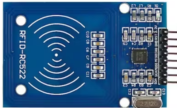
Pin Configuration
The RC522 RFID module typically has the following pinout:
| Pin Name | Description |
|---|---|
| VCC | Power supply (3.3V) |
| GND | Ground |
| RST | Reset pin (active low) |
| IRQ | Interrupt pin (optional, not always used) |
| MISO | Master In Slave Out (SPI data output) |
| MOSI | Master Out Slave In (SPI data input) |
| SCK | Serial Clock (SPI clock signal) |
| SDA/SS | Slave Select (SPI chip select) |
Usage Instructions
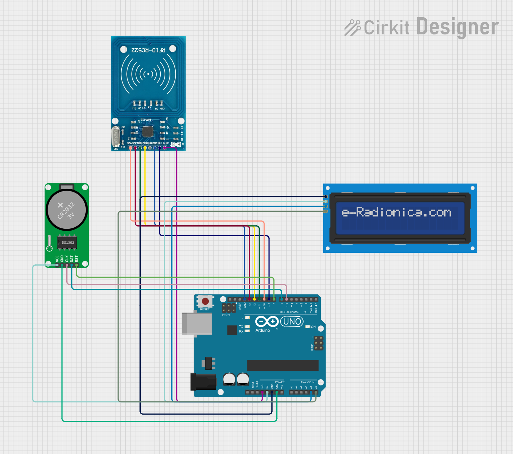
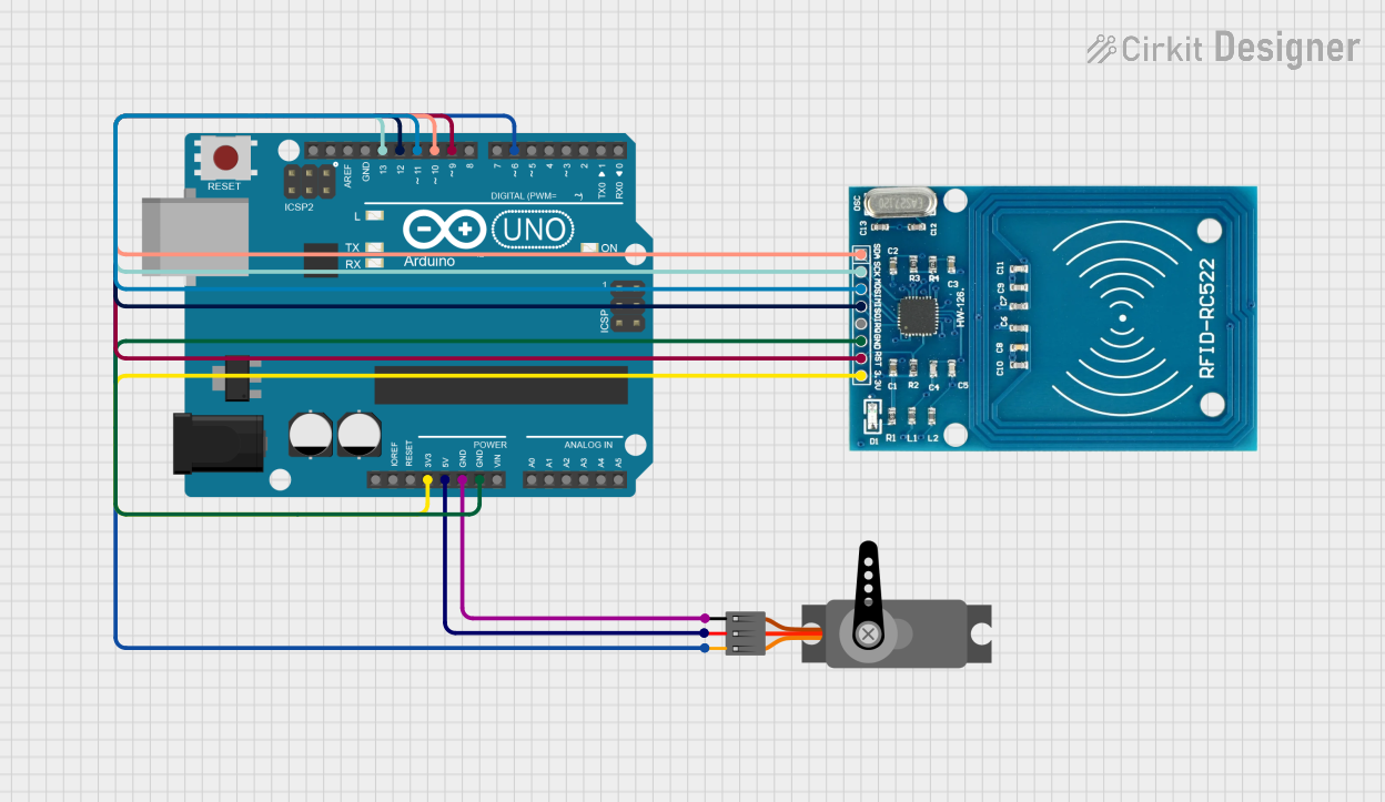
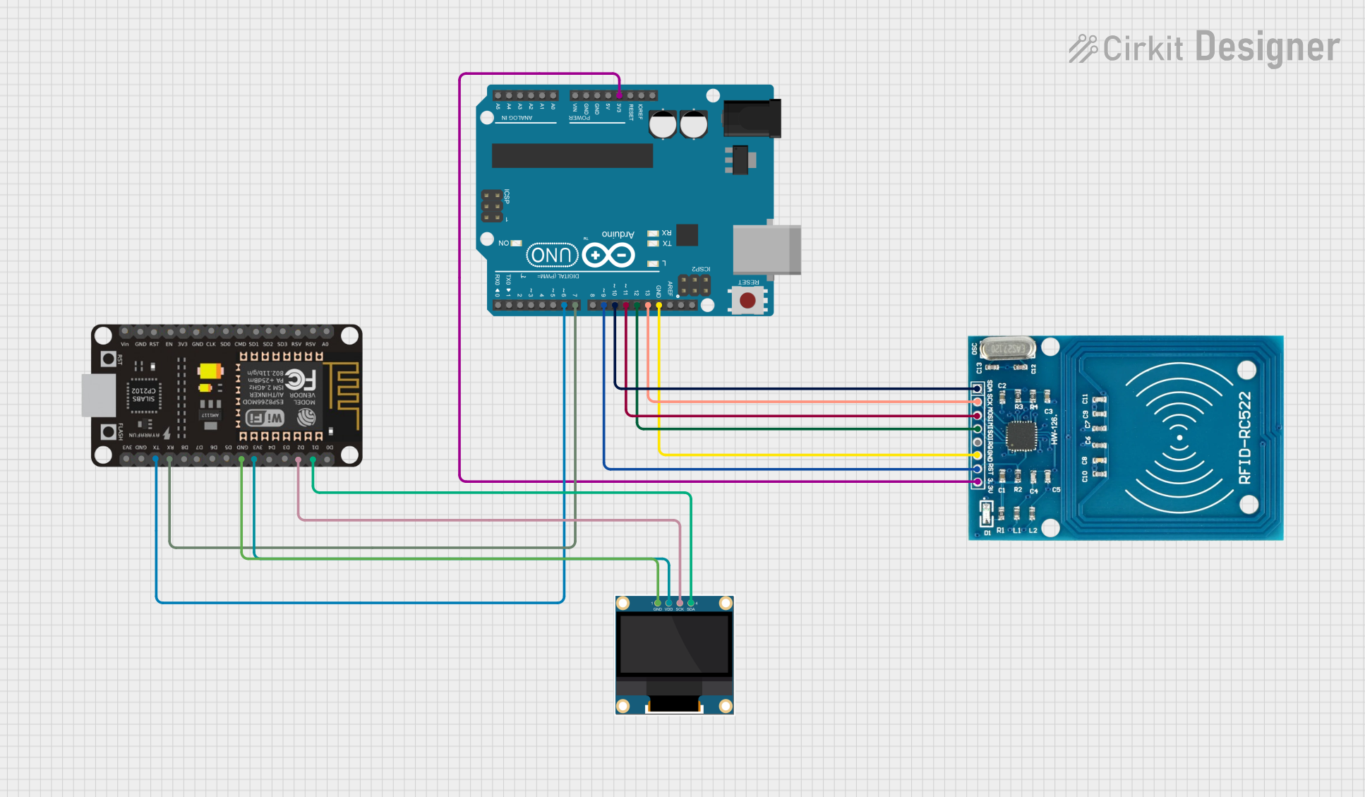
Connecting the RFID Module to an Arduino UNO
To use the RC522 RFID module with an Arduino UNO, follow these steps:
- Connect the module's pins to the Arduino as shown below:
| RC522 Pin | Arduino UNO Pin |
|---|---|
| VCC | 3.3V |
| GND | GND |
| RST | Pin 9 |
| IRQ | Not connected |
| MISO | Pin 12 |
| MOSI | Pin 11 |
| SCK | Pin 13 |
| SDA/SS | Pin 10 |
Install the "MFRC522" library in the Arduino IDE:
- Open the Arduino IDE.
- Go to Sketch > Include Library > Manage Libraries.
- Search for "MFRC522" and install the library by GithubCommunity.
Upload the following example code to your Arduino UNO:
#include <SPI.h>
#include <MFRC522.h>

// Define RFID module pins
#define RST_PIN 9  // Reset pin
#define SS_PIN 10  // Slave Select pin

MFRC522 rfid(SS_PIN, RST_PIN); // Create an instance of the RFID library

void setup() {
  Serial.begin(9600); // Initialize serial communication
  SPI.begin();        // Initialize SPI bus
  rfid.PCD_Init();    // Initialize the RFID module
  Serial.println("Place your RFID tag near the reader...");
}

void loop() {
  // Check if a new RFID tag is detected
  if (!rfid.PICC_IsNewCardPresent() || !rfid.PICC_ReadCardSerial()) {
    return; // Exit if no tag is detected
  }

  // Print the UID (Unique Identifier) of the tag
  Serial.print("Tag UID: ");
  for (byte i = 0; i < rfid.uid.size; i++) {
    Serial.print(rfid.uid.uidByte[i], HEX);
    Serial.print(" ");
  }
  Serial.println();

  // Halt the tag to stop further communication
  rfid.PICC_HaltA();
}
Important Considerations
- Ensure the RFID module is powered with 3.3V. Supplying 5V may damage the module.
- Keep the RFID tag within the specified reading distance (up to 5 cm) for reliable detection.
- Avoid placing multiple tags near the reader simultaneously, as this may cause interference.
- Use proper pull-up resistors if required for I2C communication.
Troubleshooting and FAQs
Common Issues and Solutions
The RFID module is not detected by the Arduino.
- Double-check the wiring between the RFID module and the Arduino.
- Ensure the module is powered with 3.3V, not 5V.
- Verify that the correct pins are defined in the code (
SS_PINandRST_PIN).
The RFID tag is not being read.
- Ensure the tag is compatible with the module (e.g., ISO/IEC 14443 Type A or B).
- Place the tag closer to the reader (within 5 cm).
- Check for electromagnetic interference from nearby devices.
The serial monitor shows garbled text.
- Ensure the baud rate in the Arduino IDE's serial monitor matches the code (
9600).
- Ensure the baud rate in the Arduino IDE's serial monitor matches the code (
Can I use multiple RFID modules with one Arduino?
- Yes, but you will need to assign unique
SS_PINvalues for each module and manage them in the code.
- Yes, but you will need to assign unique
What is the maximum number of tags the module can read simultaneously?
- The RC522 module is designed to read one tag at a time. Attempting to read multiple tags may result in errors.
By following this documentation, you can successfully integrate and use an RFID module in your projects.