Cirkit Designer Logo
Cirkit Designer
Your all-in-one circuit design IDE
Home / 
Component Documentation

How to Use 12V Zener Diode: Examples, Pinouts, and Specs

Image of 12V Zener Diode
Cirkit Designer LogoDesign with 12V Zener Diode in Cirkit Designer

Introduction

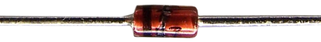
A Zener diode is a special type of semiconductor diode that permits current to flow not only from its anode to its cathode, but also in the reverse direction when the Zener voltage is reached. The 12V Zener diode is designed to maintain a stable voltage of 12 volts across its terminals, making it an essential component in voltage regulation and overvoltage protection circuits. Common applications include power supply stabilization, voltage reference in measurement devices, and protection of sensitive electronics from voltage spikes.

Explore Projects Built with 12V Zener Diode

Use Cirkit Designer to design, explore, and prototype these projects online. Some projects support real-time simulation. Click "Open Project" to start designing instantly!
Voltage Regulated Transformer Power Supply Circuit
Image of revisi 3 : A project utilizing 12V Zener Diode in a practical application
This circuit appears to be a power supply circuit with a transformer connected to a 12V battery for voltage step-up or step-down. It includes a rectification stage with a 1N4007 diode, smoothing with an electrolytic capacitor, and regulation using a Zener diode. Additionally, there are inductors for filtering and a BT139 600 triac for controlling AC power, possibly for dimming or switching applications.
Cirkit Designer LogoOpen Project in Cirkit Designer
AC to DC Power Supply with Voltage Regulation and Overcurrent Protection
Image of PENGATUR VOLTAN: A project utilizing 12V Zener Diode in a practical application
This circuit appears to be a power supply unit with a transformer for stepping down voltage, a bridge rectifier for converting AC to DC, and a voltage regulator for stabilizing the output voltage. It includes a Zener diode for overvoltage protection, capacitors for smoothing out ripples in the DC supply, and a fuse for overcurrent protection. A toggle switch and a rocker switch are used to control the power flow, and there is an LED indicator connected through resistors, likely for power-on indication.
Cirkit Designer LogoOpen Project in Cirkit Designer
Piezo Sensor-Based Voltage Measurement Circuit with 7-Segment Display
Image of piezoelectric wiring: A project utilizing 12V Zener Diode in a practical application
This circuit converts the AC signal from a piezo sensor into a DC voltage using a bridge rectifier and stabilizes it with a Zener diode. The resulting voltage is then displayed on a 7-segment panel voltmeter, with resistors used for current limiting and voltage division.
Cirkit Designer LogoOpen Project in Cirkit Designer
12V to 5V Power Supply with LED Indicator and Push Switch
Image of Power Supply LVCO: A project utilizing 12V Zener Diode in a practical application
This circuit is a 12V to 5V regulated power supply with an LED indicator. It uses a 5408 diode for reverse polarity protection, an LM340T5 7805 voltage regulator to step down the voltage to 5V, and a push switch to control the LED indicator. The circuit also includes capacitors for filtering and a resistor to limit the current through the LED.
Cirkit Designer LogoOpen Project in Cirkit Designer

Explore Projects Built with 12V Zener Diode

Use Cirkit Designer to design, explore, and prototype these projects online. Some projects support real-time simulation. Click "Open Project" to start designing instantly!
Image of revisi 3 : A project utilizing 12V Zener Diode in a practical application
Voltage Regulated Transformer Power Supply Circuit
This circuit appears to be a power supply circuit with a transformer connected to a 12V battery for voltage step-up or step-down. It includes a rectification stage with a 1N4007 diode, smoothing with an electrolytic capacitor, and regulation using a Zener diode. Additionally, there are inductors for filtering and a BT139 600 triac for controlling AC power, possibly for dimming or switching applications.
Cirkit Designer LogoOpen Project in Cirkit Designer
Image of PENGATUR VOLTAN: A project utilizing 12V Zener Diode in a practical application
AC to DC Power Supply with Voltage Regulation and Overcurrent Protection
This circuit appears to be a power supply unit with a transformer for stepping down voltage, a bridge rectifier for converting AC to DC, and a voltage regulator for stabilizing the output voltage. It includes a Zener diode for overvoltage protection, capacitors for smoothing out ripples in the DC supply, and a fuse for overcurrent protection. A toggle switch and a rocker switch are used to control the power flow, and there is an LED indicator connected through resistors, likely for power-on indication.
Cirkit Designer LogoOpen Project in Cirkit Designer
Image of piezoelectric wiring: A project utilizing 12V Zener Diode in a practical application
Piezo Sensor-Based Voltage Measurement Circuit with 7-Segment Display
This circuit converts the AC signal from a piezo sensor into a DC voltage using a bridge rectifier and stabilizes it with a Zener diode. The resulting voltage is then displayed on a 7-segment panel voltmeter, with resistors used for current limiting and voltage division.
Cirkit Designer LogoOpen Project in Cirkit Designer
Image of Power Supply LVCO: A project utilizing 12V Zener Diode in a practical application
12V to 5V Power Supply with LED Indicator and Push Switch
This circuit is a 12V to 5V regulated power supply with an LED indicator. It uses a 5408 diode for reverse polarity protection, an LM340T5 7805 voltage regulator to step down the voltage to 5V, and a push switch to control the LED indicator. The circuit also includes capacitors for filtering and a resistor to limit the current through the LED.
Cirkit Designer LogoOpen Project in Cirkit Designer

Technical Specifications

Key Technical Details

  • Nominal Zener Voltage (Vz): 12V
  • Test Current (Izt): Specified by manufacturer (e.g., 20mA)
  • Maximum Zener Impedance (Zzt): Specified by manufacturer (e.g., 5 Ohms)
  • Maximum Reverse Current (Ir): Specified at a certain voltage (e.g., 5µA at 1V)
  • Power Dissipation (Pd): Typically 0.5W to 1W (higher power ratings available)
  • Operating Temperature Range: -55°C to +150°C

Pin Configuration and Descriptions

Pin Number Name Description
1 Anode The terminal to connect to the lower potential side in forward bias
2 Cathode The terminal to connect to the higher potential side; marked by a band on the diode

Usage Instructions

How to Use the Component in a Circuit

  1. Voltage Regulation:

    • Connect the cathode of the Zener diode to the positive side of the circuit where voltage regulation is needed.
    • Connect the anode to the ground or the negative side of the circuit.
    • Place a current limiting resistor in series with the Zener diode to prevent excessive current flow.
  2. Overvoltage Protection:

    • Place the Zener diode across the load or parallel to the sensitive component.
    • Ensure the Zener diode's breakdown voltage is slightly above the normal operating voltage of the circuit.

Important Considerations and Best Practices

  • Always use a current limiting resistor to protect the Zener diode from high current that can cause overheating and damage.
  • The power rating of the Zener diode should be chosen based on the maximum power it will dissipate in the circuit.
  • For precise voltage regulation, select a Zener diode with a low dynamic impedance and test current close to the operating current.

Troubleshooting and FAQs

Common Issues

  • Excessive Heat: This may be due to overcurrent. Check the series resistor and ensure it is of the correct value.
  • Voltage Not Regulated: Ensure the Zener diode is not under the minimum current required for regulation (Izt). Also, check for any open or short circuits.

Solutions and Tips

  • Use a heat sink if the Zener diode is expected to dissipate significant power.
  • Verify the orientation of the Zener diode in the circuit; reversing it will prevent it from functioning properly.

FAQs

Q: Can I use a 12V Zener diode in a 5V circuit? A: Yes, but it will not regulate the voltage unless the supply voltage exceeds 12V.

Q: What happens if the current exceeds the maximum rating of the Zener diode? A: The diode may become damaged due to overheating. Always use a current limiting resistor.

Q: How do I choose the right current limiting resistor? A: Calculate the resistor value using Ohm's law: R = (Vsupply - Vzener) / Iz, where Iz is the desired current through the Zener diode.

Example Circuit with Arduino UNO

// Example code to demonstrate the use of a 12V Zener diode for overvoltage protection
// with an Arduino UNO. This code assumes a hypothetical sensor input that may experience
// voltage spikes.

const int sensorPin = A0; // Sensor connected to A0 pin
int sensorValue = 0;      // Variable to store the sensor value

void setup() {
  Serial.begin(9600);
}

void loop() {
  sensorValue = analogRead(sensorPin); // Read the sensor value
  Serial.println(sensorValue);         // Print the sensor value to the serial monitor
  delay(1000);                         // Wait for 1 second before the next read
}

// Note: Connect the Zener diode across the sensor output and ground with the cathode
// (marked side) to the sensor output and the anode to the ground. This will protect
// the Arduino input from voltage spikes above 12V.

Remember to keep the Zener diode's orientation correct, and ensure that the sensor output does not exceed the Arduino's maximum voltage rating (5V) under normal operating conditions. The Zener diode will clamp the voltage during spikes, protecting the microcontroller's input pin.