How to Use Emitter: Examples, Pinouts, and Specs
Introduction
The emitter is a crucial component in electronic devices, responsible for emitting electrons or other particles. It is commonly found in transistors and vacuum tubes, where it plays a vital role in facilitating the flow of current. In a transistor, the emitter is one of the three terminals (alongside the base and collector) and is typically the source of charge carriers (electrons or holes) that flow through the device.
Explore Projects Built with Emitter
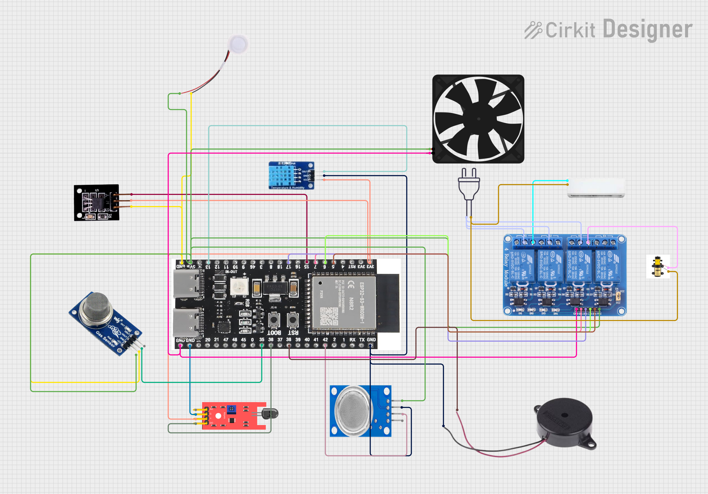
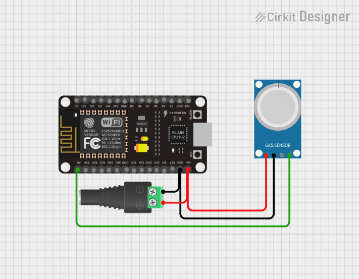

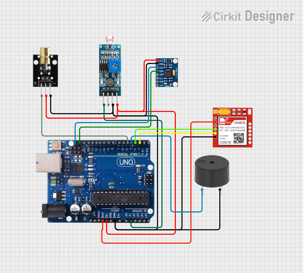
Explore Projects Built with Emitter
Common Applications and Use Cases
- Transistors (BJT and FET): Used in amplification and switching circuits.
- Vacuum Tubes: Found in older electronic devices for signal amplification.
- Current Flow Control: Essential in circuits requiring precise current regulation.
- Signal Processing: Used in analog and digital signal processing applications.
Technical Specifications
The emitter's specifications depend on the type of device it is part of (e.g., a transistor or vacuum tube). Below are general technical details for a typical emitter in a Bipolar Junction Transistor (BJT):
General Specifications
- Voltage Rating: Typically ranges from 5V to 100V, depending on the transistor type.
- Current Rating: Can handle currents from a few milliamps (mA) to several amps (A).
- Power Dissipation: Varies between 0.25W to 150W, depending on the device.
- Material: Usually made of silicon or germanium in modern transistors.
Pin Configuration and Descriptions
For a Bipolar Junction Transistor (BJT), the emitter is one of three terminals. Below is the pin configuration:
| Pin Number | Name | Description |
|---|---|---|
| 1 | Emitter | The terminal that emits charge carriers (electrons or holes) into the base. |
| 2 | Base | The control terminal that regulates the flow of charge carriers. |
| 3 | Collector | The terminal that collects charge carriers from the emitter. |
Usage Instructions
How to Use the Emitter in a Circuit
- Identify the Emitter Terminal: In a BJT, the emitter is usually marked on the package or datasheet. It is often connected to the negative terminal (NPN transistor) or positive terminal (PNP transistor) of the power supply.
- Connect the Emitter to the Circuit:
- For an NPN transistor, connect the emitter to ground or the negative rail.
- For a PNP transistor, connect the emitter to the positive rail.
- Ensure Proper Biasing: The base-emitter junction must be forward-biased for the transistor to operate correctly. This typically requires a voltage of 0.6V to 0.7V for silicon transistors.
- Add Resistors if Necessary: Use a resistor in series with the base to limit current and protect the transistor.
Important Considerations and Best Practices
- Heat Dissipation: Ensure adequate cooling for high-power applications to prevent overheating.
- Voltage and Current Ratings: Do not exceed the specified ratings to avoid damaging the component.
- Polarity: Double-check the polarity of the emitter connection to prevent reverse biasing.
- Testing: Use a multimeter to verify the emitter's connection and functionality before powering the circuit.
Example: Using an NPN Transistor with Arduino UNO
Below is an example of using an NPN transistor (e.g., 2N2222) with an Arduino UNO to control an LED:
// Example: Controlling an LED with an NPN transistor and Arduino UNO

int ledPin = 9; // Arduino pin connected to the base of the transistor
int ledState = HIGH; // Initial state of the LED

void setup() {
  pinMode(ledPin, OUTPUT); // Set the pin as an output
}

void loop() {
  digitalWrite(ledPin, ledState); // Turn the LED on or off
  delay(1000); // Wait for 1 second
  ledState = !ledState; // Toggle the LED state
}
Circuit Notes:
- Connect the emitter of the transistor to ground.
- Connect the collector to one terminal of the LED, with the other terminal connected to a resistor (e.g., 220Ω) and then to the positive supply.
- Connect the base to the Arduino pin through a 1kΩ resistor to limit current.
Troubleshooting and FAQs
Common Issues
No Current Flow Through the Emitter:
- Cause: The base-emitter junction is not forward-biased.
- Solution: Check the base voltage and ensure it is within the required range (e.g., 0.6V to 0.7V for silicon BJTs).
Overheating of the Transistor:
- Cause: Excessive current or insufficient cooling.
- Solution: Add a heat sink or reduce the current through the emitter.
Incorrect Polarity:
- Cause: The emitter is connected to the wrong terminal of the power supply.
- Solution: Verify the polarity and correct the connections.
FAQs
Q: Can the emitter be used independently of the base and collector?
A: No, the emitter is part of a transistor and requires proper interaction with the base and collector to function.
Q: How do I identify the emitter pin on a transistor?
A: Refer to the datasheet or look for markings on the transistor package. In TO-92 packages, the emitter is usually the leftmost pin when the flat side is facing you.
Q: What happens if I reverse the emitter and collector connections?
A: The transistor will not function correctly, and it may be damaged if the voltage exceeds the reverse breakdown rating.
By following this documentation, users can effectively integrate the emitter into their circuits and troubleshoot common issues.