How to Use Analog Signal Isolator PCB Module for Arduino ESP32 STM32 - 5V ISO: Examples, Pinouts, and Specs
Introduction
The Analog Signal Isolator PCB Module is a versatile electronic component designed to isolate analog signals in microcontroller-based applications. Manufactured by Arduino, this module is compatible with popular platforms such as Arduino, ESP32, and STM32. Operating at 5V, it ensures signal integrity by preventing ground loops and protecting sensitive components from voltage spikes or electrical noise.
This module is particularly useful in scenarios where analog signals need to be transmitted between circuits with different ground potentials or where electrical isolation is critical for safety and performance.
Explore Projects Built with Analog Signal Isolator PCB Module for Arduino ESP32 STM32 - 5V ISO


Explore Projects Built with Analog Signal Isolator PCB Module for Arduino ESP32 STM32 - 5V ISO
Common Applications and Use Cases
- Industrial automation and control systems
- Signal conditioning in sensor-based applications
- Noise reduction in analog signal transmission
- Protection of microcontroller inputs from high-voltage spikes
- Medical devices and instrumentation requiring electrical isolation
Technical Specifications
Key Technical Details
| Parameter | Value |
|---|---|
| Manufacturer | Arduino |
| Manufacturer Part ID | Analog Signal Isolator |
| Operating Voltage | 5V DC |
| Signal Input Range | 0-5V |
| Signal Output Range | 0-5V |
| Isolation Voltage | 2500V AC |
| Operating Temperature | -40°C to +85°C |
| Dimensions | 25mm x 20mm x 10mm |
| Compatible Platforms | Arduino, ESP32, STM32 |
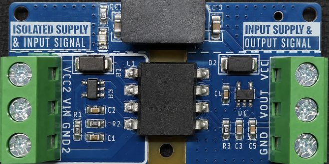
Pin Configuration and Descriptions
| Pin Name | Pin Number | Description |
|---|---|---|
| VCC | 1 | Power supply input (5V DC) |
| GND | 2 | Ground connection |
| IN+ | 3 | Positive input for the analog signal |
| IN- | 4 | Negative input for the analog signal (optional) |
| OUT+ | 5 | Positive output for the isolated analog signal |
| OUT- | 6 | Negative output for the isolated analog signal |
Usage Instructions
How to Use the Component in a Circuit
- Power the Module: Connect the
VCCpin to a 5V DC power source and theGNDpin to the ground of the power supply. - Input Signal: Connect the analog signal source to the
IN+pin. If the signal source has a differential output, connect the negative terminal to theIN-pin. - Output Signal: The isolated analog signal will be available at the
OUT+andOUT-pins. Connect these pins to the input of the receiving circuit. - Ground Isolation: Ensure that the ground of the input circuit is not directly connected to the ground of the output circuit to maintain isolation.
Important Considerations and Best Practices
- Power Supply: Use a stable 5V DC power supply to avoid introducing noise into the circuit.
- Signal Range: Ensure the input signal does not exceed the 0-5V range to prevent damage to the module.
- Isolation: Do not connect the input and output grounds directly, as this will defeat the purpose of isolation.
- Mounting: Secure the module on a PCB or breadboard to avoid loose connections.
- Testing: Verify the input and output signals using an oscilloscope to ensure proper operation.
Example Code for Arduino UNO
The following example demonstrates how to read an isolated analog signal using the Arduino UNO:
// Example: Reading an isolated analog signal using Arduino UNO

const int analogPin = A0; // Define the analog input pin (OUT+ connected here)
int analogValue = 0;      // Variable to store the analog value

void setup() {
  Serial.begin(9600); // Initialize serial communication at 9600 baud
  pinMode(analogPin, INPUT); // Set the analog pin as input
}

void loop() {
  analogValue = analogRead(analogPin); // Read the analog value from the isolator
  float voltage = (analogValue / 1023.0) * 5.0; // Convert to voltage (0-5V range)

  // Print the analog value and corresponding voltage to the Serial Monitor
  Serial.print("Analog Value: ");
  Serial.print(analogValue);
  Serial.print(" | Voltage: ");
  Serial.print(voltage);
  Serial.println(" V");

  delay(500); // Wait for 500ms before the next reading
}
Troubleshooting and FAQs
Common Issues and Solutions
| Issue | Possible Cause | Solution |
|---|---|---|
| No output signal | Incorrect wiring | Verify all connections and pin assignments. |
| Output signal is noisy | Unstable power supply | Use a regulated 5V DC power source. |
| Ground loop detected | Input and output grounds are connected | Ensure input and output grounds are isolated. |
| Signal distortion at output | Input signal exceeds 0-5V range | Limit the input signal to the specified range. |
| Module overheating | Overvoltage on VCC pin |
Ensure the power supply is 5V DC. |
FAQs
Can this module handle signals above 5V?
No, the module is designed for a 0-5V signal range. Use a voltage divider or level shifter for higher signals.Is the module compatible with 3.3V systems?
The module requires a 5V power supply, but the output can be interfaced with 3.3V systems using appropriate level shifting.Can I use this module for digital signals?
While it is optimized for analog signals, it can isolate low-frequency digital signals. However, for high-speed digital signals, consider using a dedicated digital isolator.What is the maximum isolation voltage?
The module provides an isolation voltage of up to 2500V AC, ensuring safety and reliability in high-voltage environments.How do I test the module?
Use a function generator to provide an input signal and an oscilloscope to observe the isolated output signal.
This documentation provides a comprehensive guide to understanding, using, and troubleshooting the Analog Signal Isolator PCB Module. By following the instructions and best practices outlined above, users can ensure optimal performance and reliability in their applications.