How to Use FC-51 Obstacle Sensor: Examples, Pinouts, and Specs

Introduction
The FC-51 Obstacle Sensor is an infrared proximity sensor designed for robotics and automation applications. It detects obstacles within a range of 2-40cm and provides a digital output that indicates the presence or absence of an object in its detection range. This sensor is widely utilized for obstacle avoidance in robots, line following, and object proximity detection.
Explore Projects Built with FC-51 Obstacle Sensor
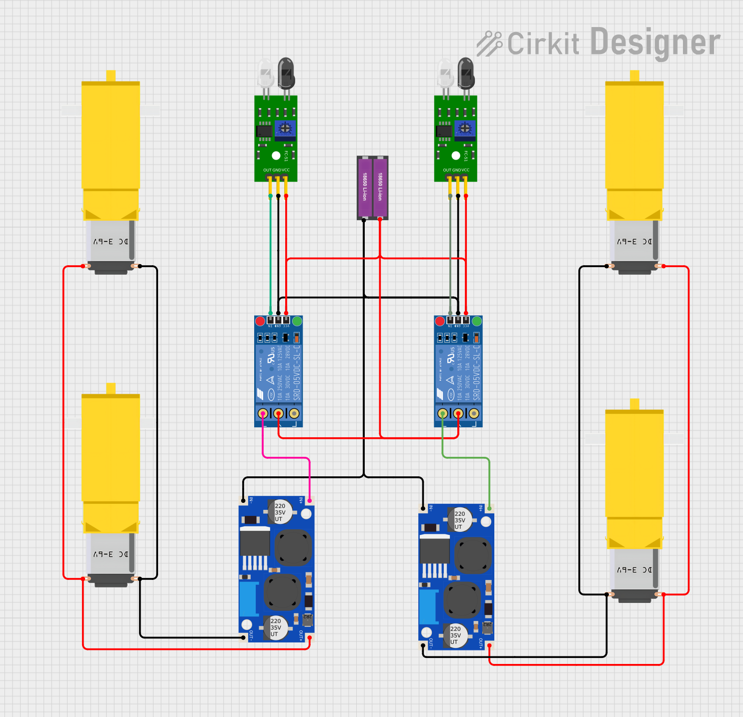
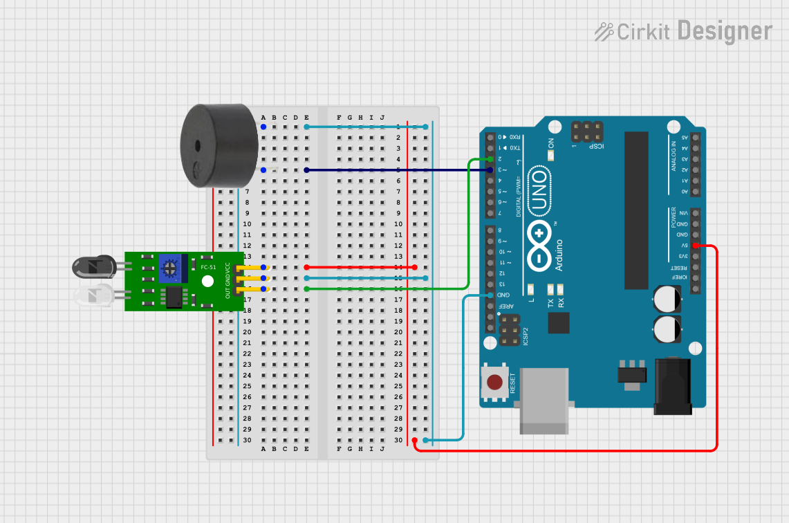
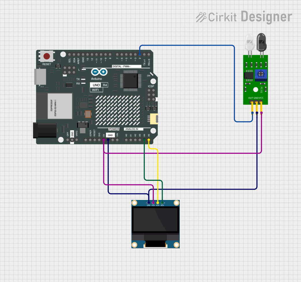
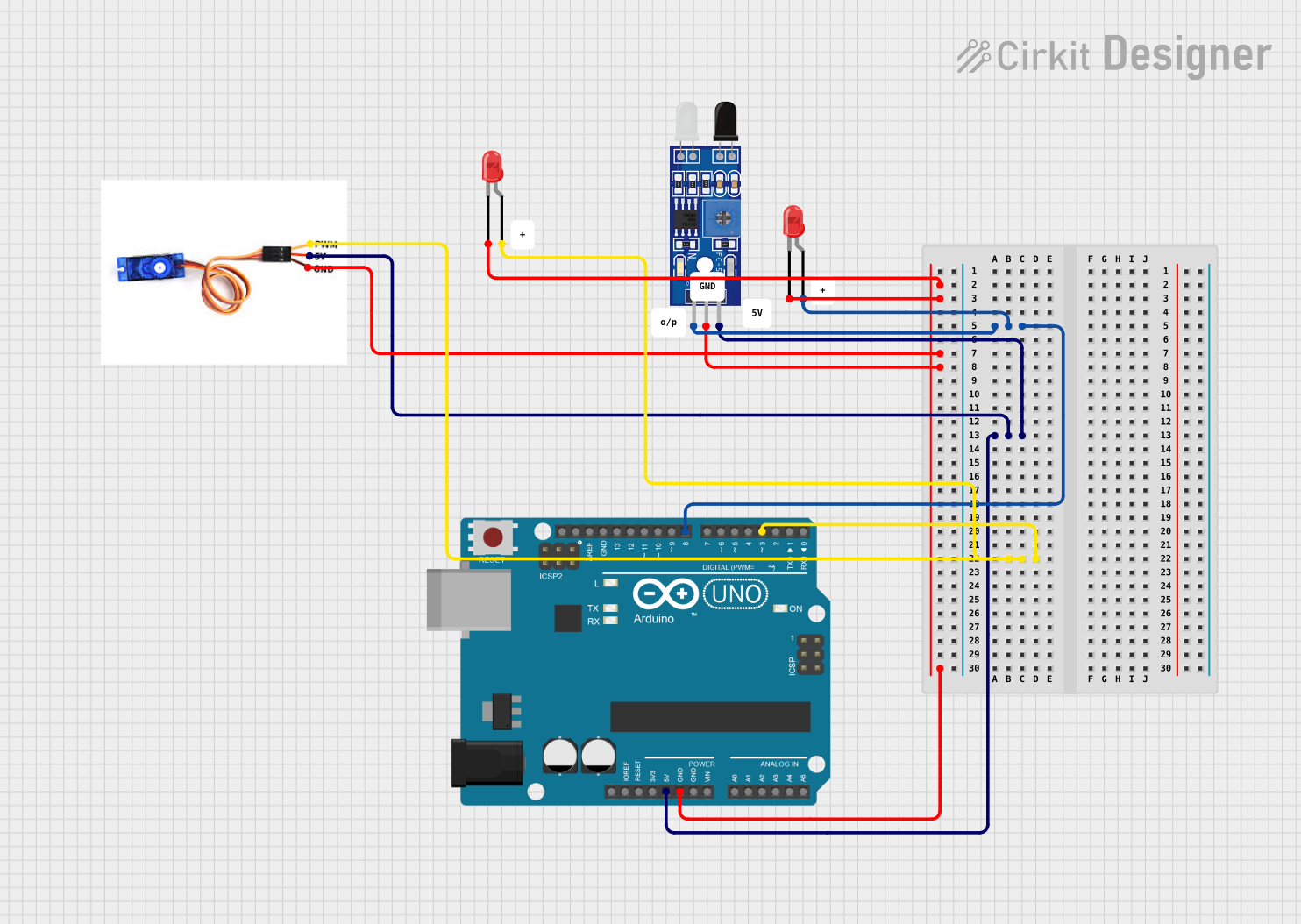
Explore Projects Built with FC-51 Obstacle Sensor
Common Applications
- Obstacle avoidance for robots
- Line following robots
- Object detection in automation systems
- Proximity sensing in interactive installations
Technical Specifications
Key Technical Details
- Operating Voltage: 5V DC
- Current Consumption: 10-15mA
- Detection Range: 2-40cm
- Output Type: Digital (High when obstacle is detected, Low when no obstacle)
- Ambient Light Resistance: Good
- Effective Angle: 35°
Pin Configuration and Descriptions
| Pin Number | Pin Name | Description |
|---|---|---|
| 1 | VCC | Power supply input (5V DC) |
| 2 | GND | Ground |
| 3 | OUT | Digital output signal (High/Low) |
Usage Instructions
Connecting to a Circuit
- Connect the VCC pin to the 5V power supply.
- Connect the GND pin to the ground of the power supply.
- Connect the OUT pin to a digital input pin on a microcontroller, such as an Arduino.
Important Considerations
- Ensure that the sensor is mounted at a height where the desired detection range is clear of any obstructions.
- Avoid exposing the sensor to direct sunlight or strong artificial light to prevent false detections.
- The sensor's detection range may vary with environmental conditions and the reflectivity of the obstacle.
Best Practices
- Use a pull-up or pull-down resistor on the OUT pin if the microcontroller input is high-impedance.
- Test the sensor's detection range with the specific obstacles you intend to detect in your application.
- Implement a debounce algorithm in your code to filter out spurious high-frequency signals.
Example Code for Arduino UNO
// Define the connection pin
const int obstacleSensorPin = 2; // FC-51 OUT pin connected to digital pin 2

void setup() {
  pinMode(obstacleSensorPin, INPUT); // Set the sensor pin as an input
  Serial.begin(9600); // Start serial communication at 9600 baud rate
}

void loop() {
  int obstacleDetected = digitalRead(obstacleSensorPin); // Read the sensor value
  if (obstacleDetected == HIGH) {
    // Obstacle detected
    Serial.println("Obstacle detected!");
  } else {
    // No obstacle detected
    Serial.println("Clear path");
  }
  delay(200); // Wait for 200 milliseconds before reading again
}
Troubleshooting and FAQs
Common Issues
- Sensor always indicates an obstacle: Check for constant sources of infrared light or reflections that might trigger the sensor.
- Sensor not responding: Ensure that the sensor is correctly powered and that the OUT pin is connected to the microcontroller.
- Inconsistent detection range: Adjust the sensor's position or check for environmental factors that may affect the infrared signal.
Solutions and Tips
- If the sensor is too sensitive, try to isolate it from other infrared sources or adjust the potentiometer on the sensor module to calibrate the detection threshold.
- For issues with the microcontroller reading, verify the pull-up or pull-down resistor configuration and check the code for proper pin initialization.
- When experiencing erratic behavior, consider adding a delay or debounce logic in the code to stabilize the output signal.
FAQs
Q: Can the FC-51 sensor detect all types of materials? A: The sensor is most effective with objects that reflect infrared light well. Transparent or highly reflective materials may not be detected reliably.
Q: Is the FC-51 sensor waterproof? A: No, the FC-51 sensor is not waterproof. Protect it from moisture and water to prevent damage.
Q: How can I adjust the detection range of the sensor? A: The sensor has a potentiometer that can be adjusted to fine-tune the detection threshold and range.
Q: Can the sensor work with 3.3V systems? A: The sensor is designed for 5V systems. Using it with 3.3V may result in reduced performance or no functionality. Use a level shifter if necessary.