How to Use Kontaktor : Examples, Pinouts, and Specs
Introduction
A kontaktor, such as the Schneider High Volt model, is an electromechanical switch designed to control large electrical loads. It is widely used in industrial applications to manage high-power devices like motors, heaters, and lighting systems. The device operates by energizing a coil, which either closes or opens its contacts, enabling or interrupting the flow of electricity. This makes kontaktors ideal for remote control of heavy electrical equipment, ensuring safety and efficiency in power management.
Explore Projects Built with Kontaktor


Explore Projects Built with Kontaktor
Common Applications and Use Cases
- Motor control in industrial machinery
- Switching high-power lighting systems
- Controlling heating elements in HVAC systems
- Automation systems in factories
- Power distribution and load management
Technical Specifications
The Schneider High Volt kontaktor is designed for robust performance in industrial environments. Below are its key technical details:
General Specifications
| Parameter | Value |
|---|---|
| Manufacturer | Schneider |
| Model | High Volt |
| Rated Voltage | 230V AC / 400V AC |
| Rated Current | 32A |
| Coil Voltage | 24V DC / 230V AC |
| Number of Poles | 3P (Three Poles) |
| Contact Type | Normally Open (NO) |
| Operating Temperature | -25°C to +60°C |
| Mechanical Durability | 10 million operations |
| Electrical Durability | 1 million operations |
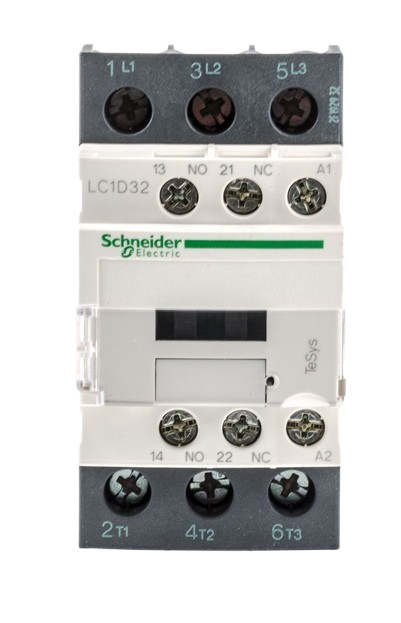
Pin Configuration and Descriptions
The Schneider High Volt kontaktor has the following pin configuration:
| Pin Label | Description |
|---|---|
| L1, L2, L3 | Input terminals for the three-phase power supply |
| T1, T2, T3 | Output terminals for the load connection |
| A1, A2 | Coil terminals for energizing the kontaktor |
| NO | Auxiliary normally open contact (optional) |
Usage Instructions
How to Use the Kontaktor in a Circuit
- Power Supply Connection: Connect the three-phase power supply to the input terminals (L1, L2, L3).
- Load Connection: Connect the load (e.g., motor, heater) to the output terminals (T1, T2, T3).
- Coil Activation: Supply the appropriate voltage (24V DC or 230V AC) to the coil terminals (A1, A2) to energize the coil and close the contacts.
- Auxiliary Contact (Optional): Use the auxiliary NO contact for signaling or control purposes in automation systems.
Important Considerations and Best Practices
- Ensure the coil voltage matches the specified rating (24V DC or 230V AC) to avoid damage.
- Use proper circuit protection devices, such as fuses or circuit breakers, to safeguard the system.
- Verify that the load current does not exceed the rated current (32A) of the kontaktor.
- Avoid exposing the device to temperatures outside the operating range (-25°C to +60°C).
- Regularly inspect the contacts for wear and replace them if necessary to maintain reliability.
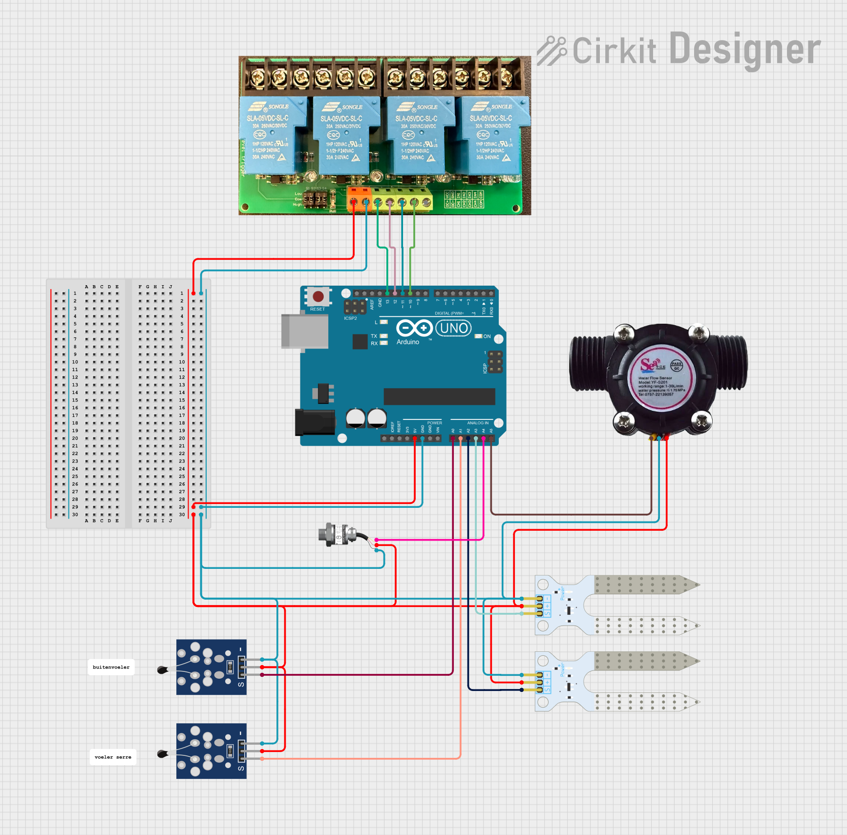
Example: Connecting the Kontaktor to an Arduino UNO
The Schneider High Volt kontaktor can be controlled using an Arduino UNO by energizing its coil with a relay module. Below is an example code snippet:
// Example code to control a kontaktor using an Arduino UNO
// The Arduino controls a relay module, which energizes the kontaktor coil.

const int relayPin = 7; // Pin connected to the relay module

void setup() {
  pinMode(relayPin, OUTPUT); // Set the relay pin as an output
  digitalWrite(relayPin, LOW); // Ensure the relay is off initially
}

void loop() {
  // Turn on the kontaktor by energizing the relay
  digitalWrite(relayPin, HIGH);
  delay(5000); // Keep the kontaktor on for 5 seconds

  // Turn off the kontaktor by de-energizing the relay
  digitalWrite(relayPin, LOW);
  delay(5000); // Keep the kontaktor off for 5 seconds
}
Note: Use a relay module that can handle the coil voltage and current of the kontaktor. Ensure proper isolation between the Arduino and the high-power circuit.
Troubleshooting and FAQs
Common Issues and Solutions
Kontaktor Does Not Energize
- Cause: Incorrect coil voltage or loose connections.
- Solution: Verify the coil voltage and ensure all connections are secure.
Contacts Overheat
- Cause: Load current exceeds the rated current (32A).
- Solution: Reduce the load or use a kontaktor with a higher current rating.
Frequent Contact Wear
- Cause: Excessive switching or arcing.
- Solution: Use arc suppression devices and limit the switching frequency.
Noise During Operation
- Cause: Loose mounting or coil vibration.
- Solution: Tighten the mounting screws and check the coil for proper operation.
FAQs
Q1: Can the Schneider High Volt kontaktor be used for single-phase loads?
A1: Yes, it can be used for single-phase loads by connecting the load to one pair of input and output terminals (e.g., L1 and T1).
Q2: How do I know if the coil is energized?
A2: You can check for an audible click or use a multimeter to measure the voltage across the coil terminals (A1, A2).
Q3: Is the kontaktor suitable for outdoor use?
A3: The Schneider High Volt kontaktor is not designed for outdoor use unless housed in a weatherproof enclosure.
Q4: Can I use the auxiliary contact for feedback to a PLC?
A4: Yes, the auxiliary NO contact can be used to provide feedback to a PLC or other control systems.