
How to Use DC-DC Buck LM2596 3A LED: Examples, Pinouts, and Specs
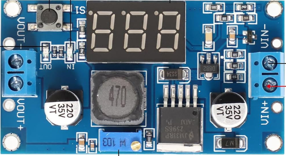
 Design with DC-DC Buck LM2596 3A LED in Cirkit Designer
Introduction
The DC-DC Buck LM2596 3A LED module is a step-down voltage regulator designed to efficiently convert a higher input voltage to a lower output voltage. It is based on the LM2596 buck converter IC and features an onboard potentiometer for precise voltage adjustment. This module is widely used in power supply circuits, battery charging systems, and LED drivers due to its high efficiency and ease of use.
Explore Projects Built with DC-DC Buck LM2596 3A LED
 Open Project in Cirkit Designer
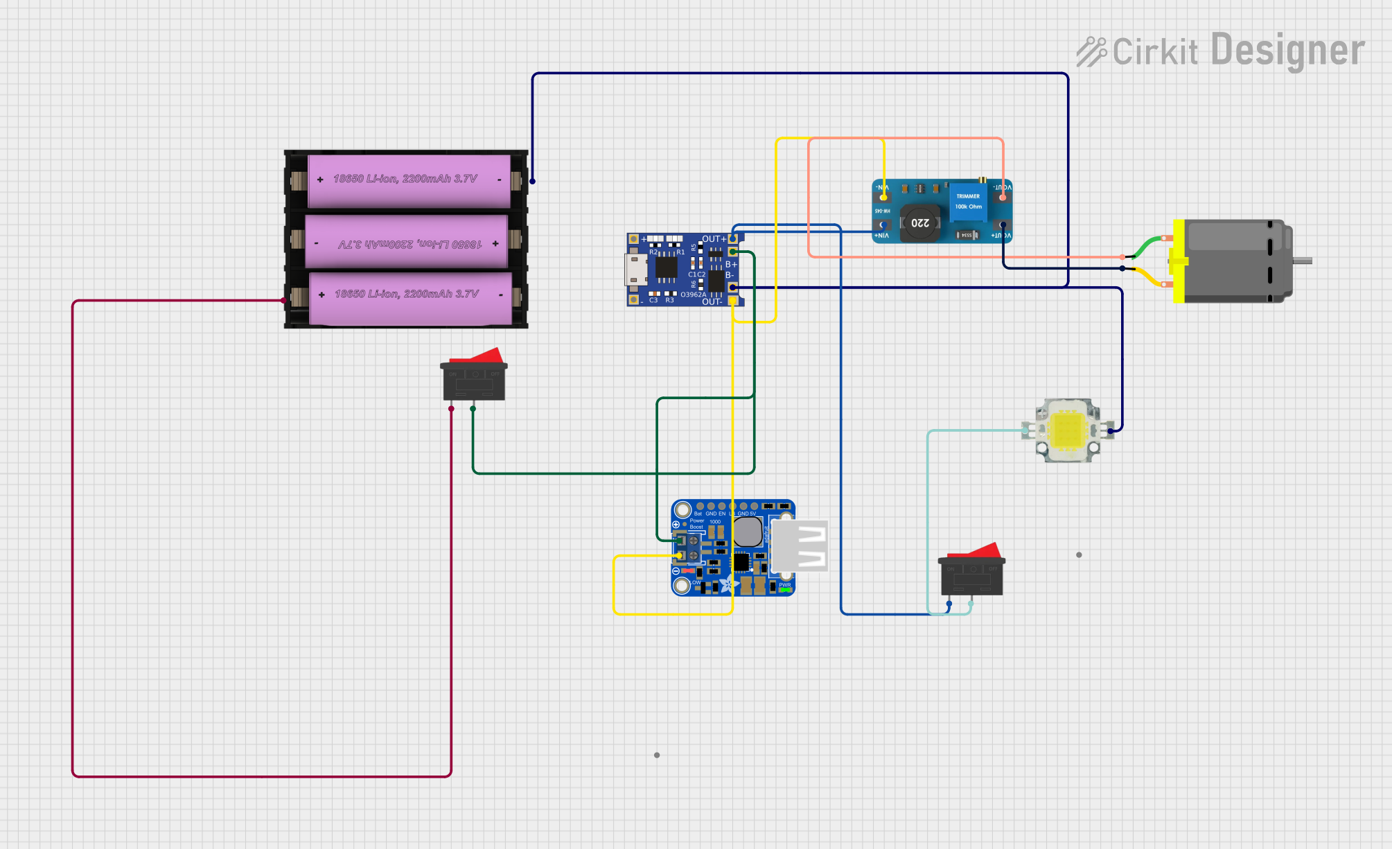 Open Project in Cirkit Designer
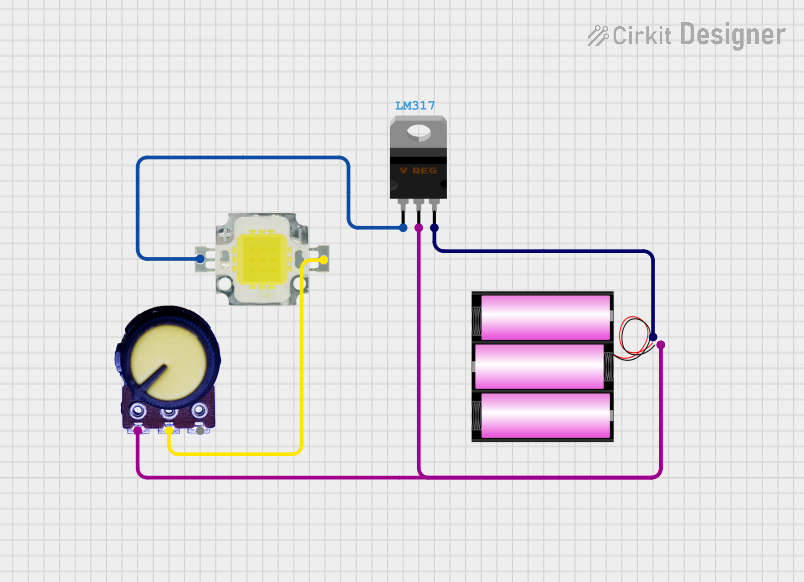 Open Project in Cirkit Designer
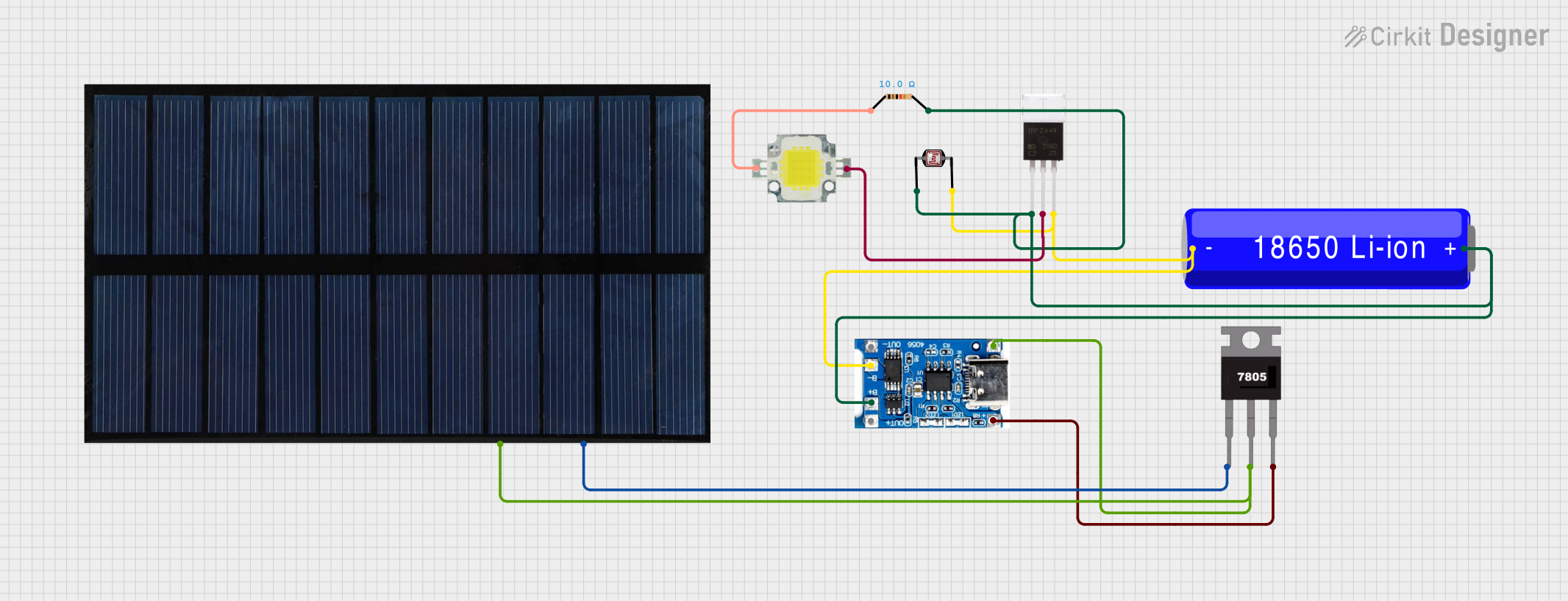 Open Project in Cirkit Designer
Explore Projects Built with DC-DC Buck LM2596 3A LED
Open Project in Cirkit DesignerOpen Project in Cirkit DesignerOpen Project in Cirkit DesignerOpen Project in Cirkit DesignerCommon Applications and Use Cases
- Powering low-voltage devices from a higher voltage source (e.g., 12V to 5V conversion)
- Battery charging circuits
- LED lighting systems
- DIY electronics projects
- Arduino and microcontroller-based applications
Technical Specifications
Key Technical Details
- Input Voltage Range: 4V to 40V DC
- Output Voltage Range: 1.25V to 37V DC (adjustable via potentiometer)
- Maximum Output Current: 3A (with proper heat dissipation)
- Efficiency: Up to 92% (depending on input/output voltage and load)
- Switching Frequency: 150 kHz
- Load Regulation: ±0.5%
- Voltage Regulation: ±2.5%
- Operating Temperature: -40°C to +85°C
Pin Configuration and Descriptions
| Pin Name | Description |
|---|---|
| IN+ | Positive input voltage terminal (connect to the higher voltage source) |
| IN- | Negative input voltage terminal (connect to the ground of the power source) |
| OUT+ | Positive output voltage terminal (connect to the load) |
| OUT- | Negative output voltage terminal (connect to the ground of the load) |
Usage Instructions
How to Use the Component in a Circuit
- Connect the Input Voltage:
- Connect the positive terminal of your power source to the
IN+pin. - Connect the ground of your power source to the
IN-pin.
- Connect the positive terminal of your power source to the
- Connect the Output Load:
- Connect the positive terminal of your load to the
OUT+pin. - Connect the ground of your load to the
OUT-pin.
- Connect the positive terminal of your load to the
- Adjust the Output Voltage:
- Use the onboard potentiometer to adjust the output voltage.
- Turn the potentiometer clockwise to increase the output voltage and counterclockwise to decrease it.
- Verify the Output Voltage:
- Use a multimeter to measure the output voltage across the
OUT+andOUT-pins. - Ensure the output voltage matches the requirements of your load.
- Use a multimeter to measure the output voltage across the
Important Considerations and Best Practices
- Heat Dissipation: If the module is operating at high currents (close to 3A), ensure proper heat dissipation by attaching a heatsink to the LM2596 IC.
- Input Voltage: Always ensure the input voltage is at least 1.5V higher than the desired output voltage for proper regulation.
- Polarity: Double-check the polarity of the input and output connections to avoid damaging the module.
- Load Current: Do not exceed the maximum output current of 3A to prevent overheating or damage.
- Arduino Integration: When using this module with an Arduino, ensure the output voltage is set to 5V or 3.3V, depending on the Arduino model.
Example: Using with Arduino UNO
To power an Arduino UNO with the LM2596 module:
- Set the output voltage of the module to 5V using the potentiometer.
- Connect the
OUT+pin to the Arduino's 5V pin. - Connect the
OUT-pin to the Arduino's GND pin. - Connect the input of the module to a 12V DC power source.
Here is an example Arduino code to blink an LED while powered by the LM2596 module:
// Blink an LED connected to pin 13 of the Arduino UNO
// Ensure the LM2596 module is providing a stable 5V to the Arduino

void setup() {
  pinMode(13, OUTPUT); // Set pin 13 as an output pin
}

void loop() {
  digitalWrite(13, HIGH); // Turn the LED on
  delay(1000);            // Wait for 1 second
  digitalWrite(13, LOW);  // Turn the LED off
  delay(1000);            // Wait for 1 second
}
Troubleshooting and FAQs
Common Issues and Solutions
No Output Voltage:
- Cause: Incorrect input connections or insufficient input voltage.
- Solution: Verify the input connections and ensure the input voltage is within the specified range.
Output Voltage Not Adjustable:
- Cause: Faulty potentiometer or incorrect adjustment.
- Solution: Gently turn the potentiometer and ensure it is not damaged.
Overheating:
- Cause: Excessive load current or insufficient heat dissipation.
- Solution: Reduce the load current or attach a heatsink to the LM2596 IC.
Voltage Drop Under Load:
- Cause: Input voltage too low or load current exceeds the module's capacity.
- Solution: Increase the input voltage or reduce the load current.
FAQs
Can I use this module to charge a battery? Yes, but ensure the output voltage is set to the appropriate charging voltage for the battery type.
What happens if I reverse the input polarity? The module does not have reverse polarity protection and may be damaged. Always double-check the polarity before powering the module.
Can I use this module with a solar panel? Yes, as long as the solar panel's output voltage is within the module's input voltage range.
Is the module safe for powering sensitive electronics? Yes, but it is recommended to add a capacitor at the output for additional filtering to reduce noise.