How to Use SW-420 Vibration Sensor: Examples, Pinouts, and Specs
Introduction
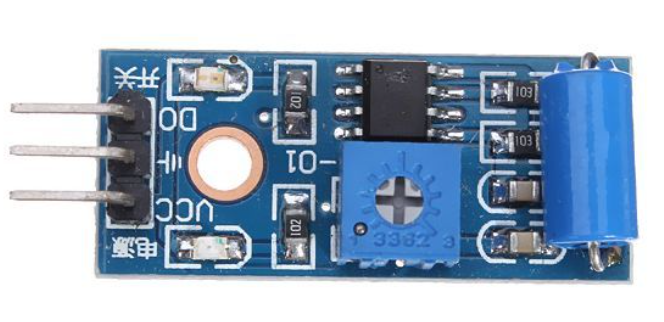
The SW-420 Vibration Sensor is a device designed to detect vibrations and shocks. It is commonly used in security systems, industrial applications, and various projects requiring motion detection. This sensor is highly sensitive and can detect even minor vibrations, making it ideal for applications where precise motion detection is crucial.
Explore Projects Built with SW-420 Vibration Sensor
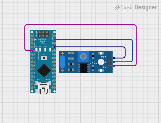
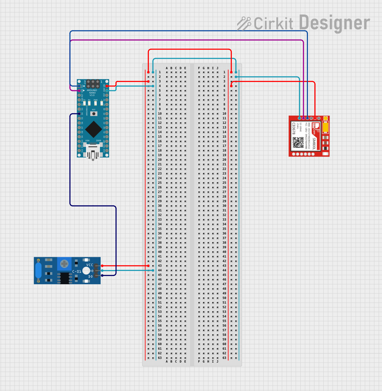
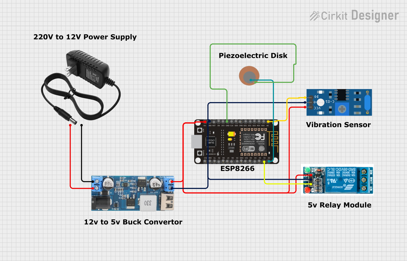
Explore Projects Built with SW-420 Vibration Sensor
Technical Specifications
Key Technical Details
| Parameter | Value |
|---|---|
| Operating Voltage | 3.3V - 5V |
| Output Type | Digital (High/Low) |
| Sensitivity | Adjustable via potentiometer |
| Dimensions | 32mm x 14mm x 8mm |
| Operating Temperature | -10°C to +70°C |
Pin Configuration and Descriptions
| Pin Number | Pin Name | Description |
|---|---|---|
| 1 | VCC | Power supply (3.3V - 5V) |
| 2 | GND | Ground |
| 3 | DO | Digital Output (High/Low) |
Usage Instructions
How to Use the Component in a Circuit
- Power Supply: Connect the VCC pin to a 3.3V or 5V power supply.
- Ground: Connect the GND pin to the ground of the circuit.
- Digital Output: Connect the DO pin to a digital input pin on your microcontroller (e.g., Arduino).
Example Circuit with Arduino UNO
Arduino UNO       SW-420 Vibration Sensor
-----------       -----------------------
5V                -> VCC
GND               -> GND
Digital Pin 2     -> DO
Sample Code for Arduino UNO
// SW-420 Vibration Sensor Example Code
const int sensorPin = 2; // Pin connected to DO pin of SW-420
const int ledPin = 13;   // Onboard LED pin

void setup() {
  pinMode(sensorPin, INPUT); // Set sensor pin as input
  pinMode(ledPin, OUTPUT);   // Set LED pin as output
  Serial.begin(9600);        // Initialize serial communication
}

void loop() {
  int sensorState = digitalRead(sensorPin); // Read sensor state
  if (sensorState == HIGH) {
    digitalWrite(ledPin, HIGH); // Turn on LED if vibration detected
    Serial.println("Vibration Detected!");
  } else {
    digitalWrite(ledPin, LOW);  // Turn off LED if no vibration
  }
  delay(100); // Small delay to debounce sensor
}
Important Considerations and Best Practices
- Power Supply: Ensure the sensor is powered within the specified voltage range (3.3V - 5V).
- Mounting: Securely mount the sensor to avoid false triggers due to loose connections.
- Sensitivity Adjustment: Use the onboard potentiometer to adjust the sensitivity according to your application needs.
- Debouncing: Implement debouncing in your code to avoid multiple triggers from a single vibration event.
Troubleshooting and FAQs
Common Issues and Solutions
No Output Signal:
- Check Connections: Ensure all connections are secure and correct.
- Power Supply: Verify that the sensor is receiving the correct voltage.
False Triggers:
- Sensitivity Adjustment: Adjust the potentiometer to reduce sensitivity.
- Debouncing: Implement debouncing in your code to filter out noise.
Intermittent Output:
- Stable Mounting: Ensure the sensor is securely mounted to avoid intermittent connections.
- Power Supply Stability: Ensure a stable power supply to the sensor.
FAQs
Q1: Can the SW-420 Vibration Sensor detect continuous vibrations?
- A1: Yes, the sensor can detect continuous vibrations, but it is primarily designed for detecting sudden shocks and movements.
Q2: How do I adjust the sensitivity of the sensor?
- A2: The sensitivity can be adjusted using the onboard potentiometer. Turn it clockwise to increase sensitivity and counterclockwise to decrease it.
Q3: Can I use the SW-420 Vibration Sensor with a 3.3V microcontroller?
- A3: Yes, the sensor can operate at both 3.3V and 5V, making it compatible with a wide range of microcontrollers.
By following this documentation, users can effectively integrate the SW-420 Vibration Sensor into their projects, ensuring reliable motion detection and optimal performance.