How to Use Lora Ra-01: Examples, Pinouts, and Specs
Introduction
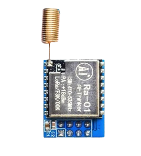
The Lora Ra-01 is a long-range, low-power wireless communication module designed for IoT (Internet of Things) applications. Manufactured by Lora and based on the SX1278 chipset, this module leverages the LoRa (Long Range) protocol to enable robust communication over distances of several kilometers. Its low power consumption makes it ideal for battery-powered devices and remote deployments.
Explore Projects Built with Lora Ra-01

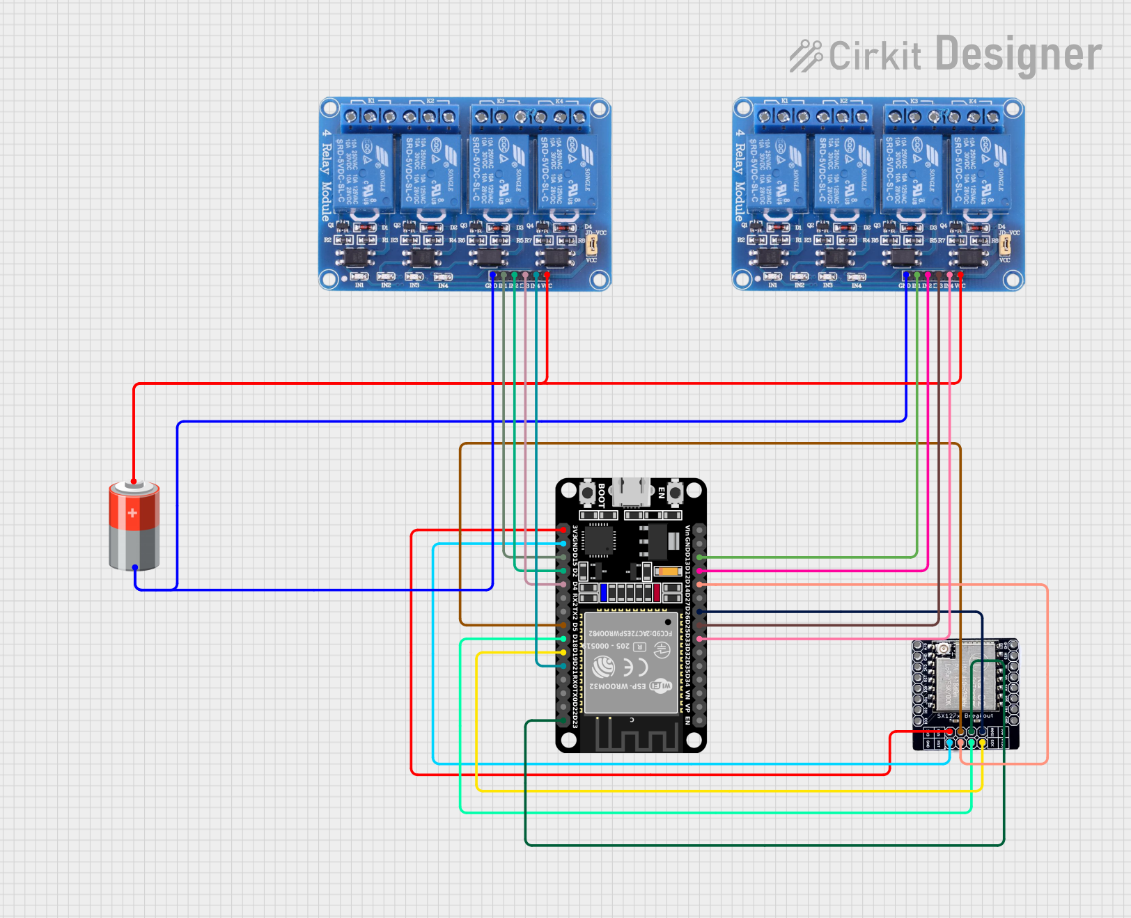
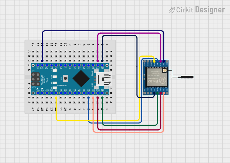
Explore Projects Built with Lora Ra-01
Common Applications and Use Cases
- Remote sensor networks (e.g., environmental monitoring, agriculture)
- Smart city applications (e.g., smart lighting, parking systems)
- Industrial IoT (e.g., predictive maintenance, asset tracking)
- Home automation and security systems
- Long-range wireless communication for hobbyist projects
Technical Specifications
The Lora Ra-01 module is built for reliable and efficient communication. Below are its key technical details:
| Parameter | Value |
|---|---|
| Chipset | SX1278 |
| Frequency Range | 433 MHz (default) |
| Modulation Technique | LoRa (Long Range) |
| Communication Range | Up to 10 km (line of sight) |
| Data Rate | 0.3 kbps to 37.5 kbps |
| Supply Voltage | 1.8V to 3.7V |
| Operating Current | 10.8 mA (transmit mode) |
| Sleep Current | < 200 nA |
| Output Power | Up to +20 dBm |
| Sensitivity | -148 dBm |
| Operating Temperature | -40°C to +85°C |
| Interface | SPI |
Pin Configuration and Descriptions
The Lora Ra-01 module has 16 pins. Below is the pinout and description:
| Pin Number | Pin Name | Description |
|---|---|---|
| 1 | GND | Ground connection |
| 2 | DIO0 | Digital I/O pin 0 (interrupt output) |
| 3 | DIO1 | Digital I/O pin 1 |
| 4 | DIO2 | Digital I/O pin 2 |
| 5 | DIO3 | Digital I/O pin 3 |
| 6 | DIO4 | Digital I/O pin 4 |
| 7 | DIO5 | Digital I/O pin 5 |
| 8 | 3.3V | Power supply (1.8V to 3.7V) |
| 9 | RESET | Reset pin (active low) |
| 10 | NSS | SPI chip select |
| 11 | SCK | SPI clock |
| 12 | MOSI | SPI master out, slave in |
| 13 | MISO | SPI master in, slave out |
| 14 | GND | Ground connection |
| 15 | ANT | Antenna connection |
| 16 | NC | Not connected |
Usage Instructions
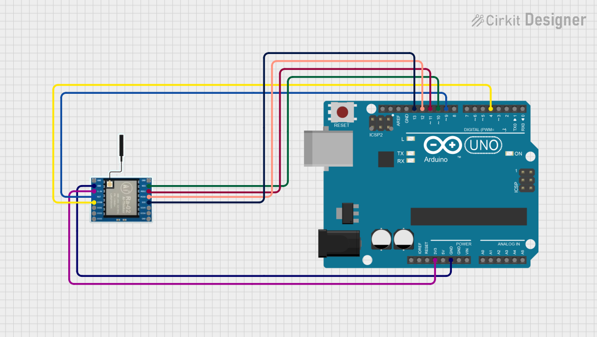
The Lora Ra-01 module is typically used in conjunction with a microcontroller, such as an Arduino UNO, to enable wireless communication. Below are the steps to use the module in a circuit:
Connecting the Lora Ra-01 to an Arduino UNO
- Power Supply: Connect the
3.3Vpin of the module to the3.3Vpin on the Arduino. Do not use the5Vpin, as it may damage the module. - Ground: Connect the
GNDpin of the module to theGNDpin on the Arduino. - SPI Interface: Connect the SPI pins of the module to the corresponding pins on the Arduino:
NSS→ Pin 10 (Chip Select)SCK→ Pin 13 (Clock)MOSI→ Pin 11 (Master Out, Slave In)MISO→ Pin 12 (Master In, Slave Out)
- Reset and Interrupts: Connect the
RESETpin to a digital pin (e.g., Pin 9) and theDIO0pin to another digital pin (e.g., Pin 2) for handling interrupts.
Example Arduino Code
Below is an example of how to use the Lora Ra-01 module with the Arduino UNO using the RadioHead library:
#include <SPI.h>
#include <RH_RF95.h>

// Define pins for the Lora Ra-01 module
#define RFM95_CS 10    // NSS pin
#define RFM95_RST 9    // Reset pin
#define RFM95_INT 2    // DIO0 pin

// Define frequency (433 MHz for Lora Ra-01)
#define RF95_FREQ 433.0

// Create an instance of the RF95 driver
RH_RF95 rf95(RFM95_CS, RFM95_INT);

void setup() {
  // Initialize serial communication
  Serial.begin(9600);
  while (!Serial);

  // Initialize the reset pin
  pinMode(RFM95_RST, OUTPUT);
  digitalWrite(RFM95_RST, HIGH);

  // Reset the module
  digitalWrite(RFM95_RST, LOW);
  delay(10);
  digitalWrite(RFM95_RST, HIGH);
  delay(10);

  // Initialize the RF95 module
  if (!rf95.init()) {
    Serial.println("LoRa initialization failed!");
    while (1);
  }
  Serial.println("LoRa initialization successful!");

  // Set the frequency
  if (!rf95.setFrequency(RF95_FREQ)) {
    Serial.println("Frequency set failed!");
    while (1);
  }
  Serial.print("Frequency set to: ");
  Serial.println(RF95_FREQ);

  // Set the transmission power
  rf95.setTxPower(20, false);
}

void loop() {
  // Send a message
  const char *message = "Hello, LoRa!";
  rf95.send((uint8_t *)message, strlen(message));
  rf95.waitPacketSent();
  Serial.println("Message sent!");

  // Wait for a response
  if (rf95.waitAvailableTimeout(3000)) {
    uint8_t buf[RH_RF95_MAX_MESSAGE_LEN];
    uint8_t len = sizeof(buf);
    if (rf95.recv(buf, &len)) {
      Serial.print("Received: ");
      Serial.println((char *)buf);
    } else {
      Serial.println("Receive failed!");
    }
  } else {
    Serial.println("No response received.");
  }

  delay(5000); // Wait 5 seconds before sending the next message
}
Important Considerations and Best Practices
- Power Supply: Ensure the module is powered with 3.3V. Using 5V can permanently damage the module.
- Antenna: Always connect an appropriate antenna to the
ANTpin to ensure proper operation and avoid damage to the module. - SPI Communication: Ensure the SPI pins are correctly connected and configured in your code.
- Range Optimization: For maximum range, use a clear line of sight and minimize interference from obstacles or other RF devices.
Troubleshooting and FAQs
Common Issues and Solutions
Module Not Responding
- Cause: Incorrect wiring or power supply.
- Solution: Double-check all connections and ensure the module is powered with 3.3V.
Poor Communication Range
- Cause: Improper antenna or environmental interference.
- Solution: Use a high-quality antenna and ensure a clear line of sight between devices.
SPI Communication Fails
- Cause: Incorrect SPI pin configuration or library issues.
- Solution: Verify the SPI connections and ensure the correct pins are defined in the code.
No Response from Receiver
- Cause: Frequency mismatch or incorrect settings.
- Solution: Ensure both transmitter and receiver are set to the same frequency and modulation parameters.
FAQs
Can I use the Lora Ra-01 with a 5V microcontroller?
- Yes, but you must use a level shifter to convert the 5V logic to 3.3V for the module.
What is the maximum range of the Lora Ra-01?
- The module can achieve up to 10 km in ideal conditions (line of sight).
Is the Lora Ra-01 compatible with other LoRa modules?
- Yes, as long as they operate on the same frequency and use the LoRa protocol.