
How to Use ADL400 3 phase AC energy meter direct current: Examples, Pinouts, and Specs
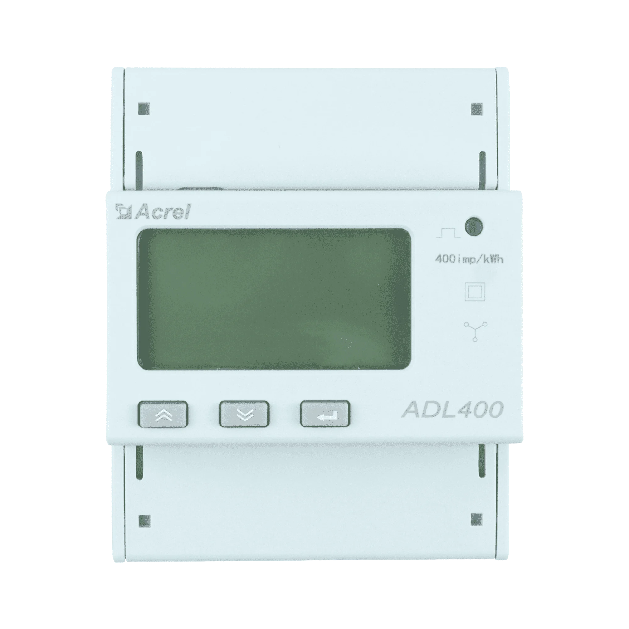
 Design with ADL400 3 phase AC energy meter direct current in Cirkit Designer
Introduction
The ADL400 is a three-phase AC energy meter manufactured by Acrel. It is designed to measure energy consumption in three-phase electrical systems with high accuracy. This device provides real-time readings of voltage, current, power factor, active power, and reactive power, making it an essential tool for energy monitoring and management in industrial, commercial, and residential applications.
Explore Projects Built with ADL400 3 phase AC energy meter direct current
 Open Project in Cirkit Designer
 Open Project in Cirkit Designer
 Open Project in Cirkit Designer
 Open Project in Cirkit Designer
Explore Projects Built with ADL400 3 phase AC energy meter direct current
Open Project in Cirkit DesignerOpen Project in Cirkit DesignerOpen Project in Cirkit DesignerOpen Project in Cirkit DesignerCommon Applications and Use Cases
- Energy consumption monitoring in industrial facilities
- Power management in commercial buildings
- Sub-metering in residential complexes
- Renewable energy systems monitoring
- Integration with building management systems (BMS)
Technical Specifications
The following table outlines the key technical specifications of the ADL400:
| Parameter | Specification |
|---|---|
| Manufacturer | Acrel |
| Part ID | ADL400 |
| Voltage Range | 3 × 220V/380V AC |
| Current Range | 1.5(6)A or 10(100)A |
| Frequency | 50/60 Hz |
| Accuracy Class | Class 1 (active energy) |
| Power Consumption | ≤ 2W / 10VA |
| Communication Interface | RS485 (Modbus-RTU protocol) |
| Display | LCD with backlight |
| Operating Temperature | -25°C to +55°C |
| Storage Temperature | -40°C to +70°C |
| Dimensions | 100mm × 72mm × 65mm |
| Mounting Type | DIN rail |
Pin Configuration and Descriptions
The ADL400 features terminals for connecting to the three-phase system and communication interfaces. Below is the pin configuration:
| Terminal | Description |
|---|---|
| L1, L2, L3 | Phase inputs for the three-phase AC system |
| N | Neutral input |
| I1, I2, I3 | Current transformer (CT) inputs for each phase |
| RS485+ | RS485 communication positive terminal |
| RS485- | RS485 communication negative terminal |
| AUX+ | Auxiliary power supply positive terminal (optional) |
| AUX- | Auxiliary power supply negative terminal (optional) |
Usage Instructions
How to Use the ADL400 in a Circuit
- Mounting: Install the ADL400 on a DIN rail in a suitable enclosure to protect it from environmental factors.
- Wiring:
- Connect the phase wires (L1, L2, L3) and neutral (N) to the corresponding terminals.
- If using current transformers (CTs), connect the CT outputs to the I1, I2, and I3 terminals.
- For communication, connect the RS485+ and RS485- terminals to the RS485 network.
- Powering the Device: Ensure the device is powered by the connected three-phase system or an auxiliary power supply if required.
- Configuration:
- Use the front-panel buttons to navigate the LCD menu and configure parameters such as CT ratio, communication address, and baud rate.
- Alternatively, configure the device via the RS485 interface using Modbus-RTU commands.
Important Considerations and Best Practices
- Ensure proper grounding to avoid electrical noise interference.
- Verify the CT ratio settings match the installed CTs for accurate measurements.
- Avoid exceeding the rated voltage and current limits to prevent damage.
- Use shielded cables for RS485 communication to minimize signal interference.
- Regularly inspect the wiring connections to ensure they are secure and free from corrosion.
Arduino UNO Integration Example
The ADL400 can be connected to an Arduino UNO via the RS485 interface for data logging and monitoring. Below is an example code snippet to read voltage data using the Modbus-RTU protocol:
#include <ModbusMaster.h>

// Instantiate ModbusMaster object
ModbusMaster node;

// Define RS485 communication pins
#define RE_PIN 2  // Receiver Enable pin
#define DE_PIN 3  // Driver Enable pin

void preTransmission() {
  digitalWrite(RE_PIN, HIGH); // Enable RS485 transmitter
  digitalWrite(DE_PIN, HIGH);
}

void postTransmission() {
  digitalWrite(RE_PIN, LOW);  // Disable RS485 transmitter
  digitalWrite(DE_PIN, LOW);
}

void setup() {
  // Initialize serial communication
  Serial.begin(9600);
  Serial.println("ADL400 Energy Meter Reading");

  // Initialize RS485 communication
  pinMode(RE_PIN, OUTPUT);
  pinMode(DE_PIN, OUTPUT);
  digitalWrite(RE_PIN, LOW);
  digitalWrite(DE_PIN, LOW);

  // Configure Modbus communication
  node.begin(1, Serial); // Set Modbus ID to 1
  node.preTransmission(preTransmission);
  node.postTransmission(postTransmission);
}

void loop() {
  uint8_t result;
  uint16_t data;

  // Read voltage from register 0x0000 (example register address)
  result = node.readInputRegisters(0x0000, 1);

  if (result == node.ku8MBSuccess) {
    data = node.getResponseBuffer(0);
    Serial.print("Voltage: ");
    Serial.print(data / 10.0); // Convert to volts (example scaling)
    Serial.println(" V");
  } else {
    Serial.println("Failed to read data from ADL400");
  }

  delay(1000); // Wait 1 second before next reading
}
Troubleshooting and FAQs
Common Issues and Solutions
No Display on LCD:
- Check the power supply connections and ensure the device is receiving the correct voltage.
- Verify that the auxiliary power supply (if used) is functioning properly.
Incorrect Readings:
- Ensure the CTs are properly connected and the CT ratio is correctly configured.
- Verify that the phase and neutral connections are secure and not reversed.
Communication Failure:
- Check the RS485 wiring for loose or incorrect connections.
- Ensure the Modbus address and baud rate settings match the master device configuration.
- Use shielded cables to reduce interference.
Device Overheating:
- Ensure the device is installed in a well-ventilated area.
- Verify that the current and voltage do not exceed the rated limits.
FAQs
Q: Can the ADL400 measure single-phase systems?
A: No, the ADL400 is specifically designed for three-phase systems. For single-phase applications, consider using a single-phase energy meter.
Q: What is the maximum communication distance for RS485?
A: The RS485 interface supports a maximum communication distance of up to 1200 meters, depending on cable quality and environmental conditions.
Q: How do I reset the energy readings?
A: Energy readings can be reset via the front-panel menu or by sending the appropriate Modbus command through the RS485 interface.
Q: Is the ADL400 compatible with solar inverters?
A: Yes, the ADL400 can be used to monitor energy consumption in systems with solar inverters, provided the voltage and current ratings are within the device's specifications.