
Cirkit Designer
Your all-in-one circuit design IDE
Home /
Component Documentation
How to Use E Stop: Examples, Pinouts, and Specs
 Design with E Stop in Cirkit Designer
Introduction
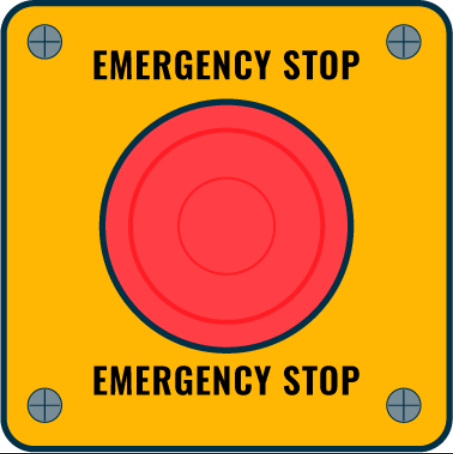
- The E Stop, or Emergency Stop switch, is a safety device designed to immediately cut power to a machine or circuit in case of an emergency. It is a critical component in industrial, commercial, and even some consumer applications where safety is paramount.
- Common applications include industrial machinery, conveyor systems, robotics, and any equipment where rapid shutdown is necessary to prevent injury or damage.
Explore Projects Built with E Stop
ESP32-Based Sensor Monitoring System with OLED Display and E-Stop
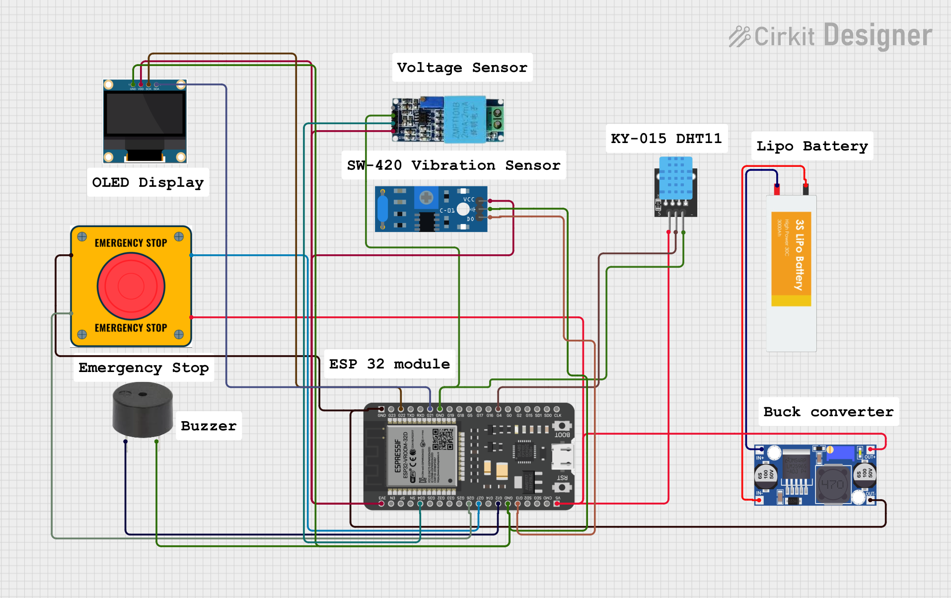
This circuit features an ESP32 microcontroller that interfaces with a variety of sensors and output devices. It is powered by a Lipo battery through a buck converter, ensuring a stable voltage supply. The ESP32 collects data from a DHT11 temperature and humidity sensor and a vibration sensor, controls a buzzer, and displays information on an OLED screen. An emergency stop (E Stop) is connected for safety purposes, allowing the system to be quickly deactivated.
Open Project in Cirkit DesignerElectromechanical Pump Control Circuit with Emergency Stop
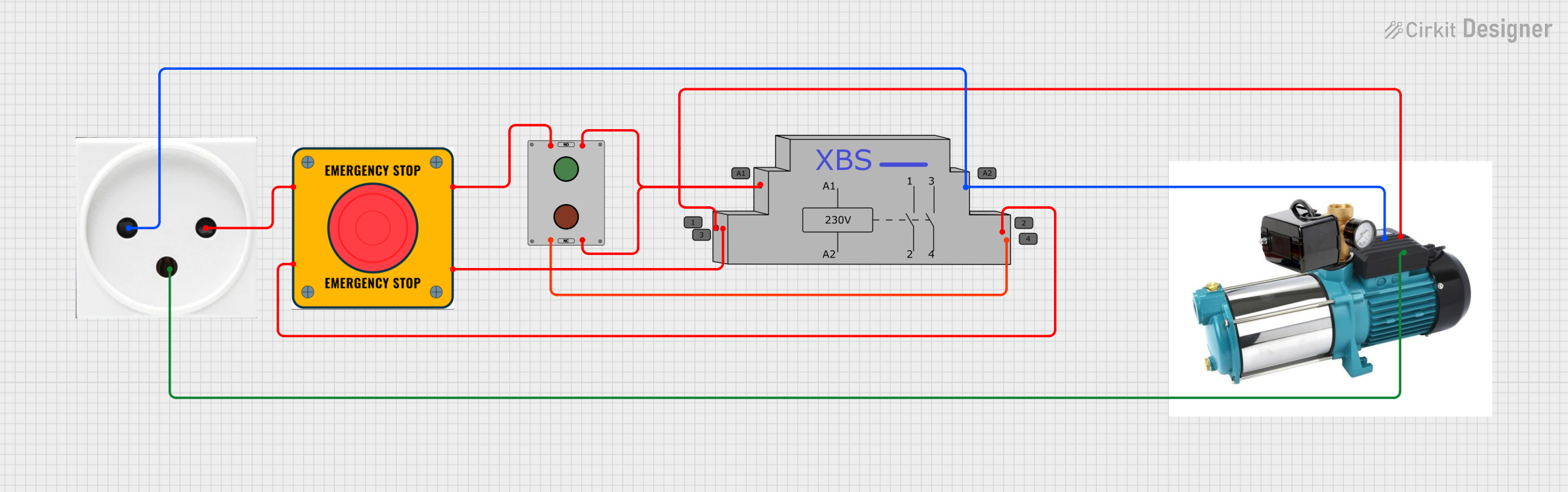
This circuit is designed to control a pump using a contactor that is manually operated by a switch and can be overridden by an emergency stop. The contactor enables power from an AC power outlet to the pump, and the emergency stop can interrupt the power circuit for safety purposes.
Open Project in Cirkit DesignerESP32-Based Environmental Monitoring System with Emergency Stop and Display
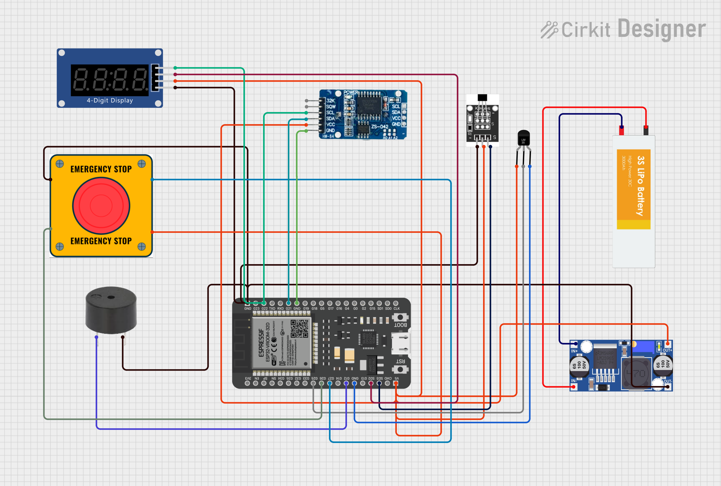
This circuit features an ESP32 microcontroller interfaced with various sensors and output devices. A temperature sensor (LM35) and a hall sensor provide environmental data, while a real-time clock (RTC DS3231) keeps track of time. The circuit includes a buck converter to regulate power from a LiPo battery, an emergency stop (E Stop) for safety, a buzzer for audible alerts, and a seven-segment display (TM1637) for visual feedback. The ESP32 manages sensor readings, time tracking, and user interface components.
Open Project in Cirkit DesignerESP32-Based Smart Environmental Monitoring System with Relay Control
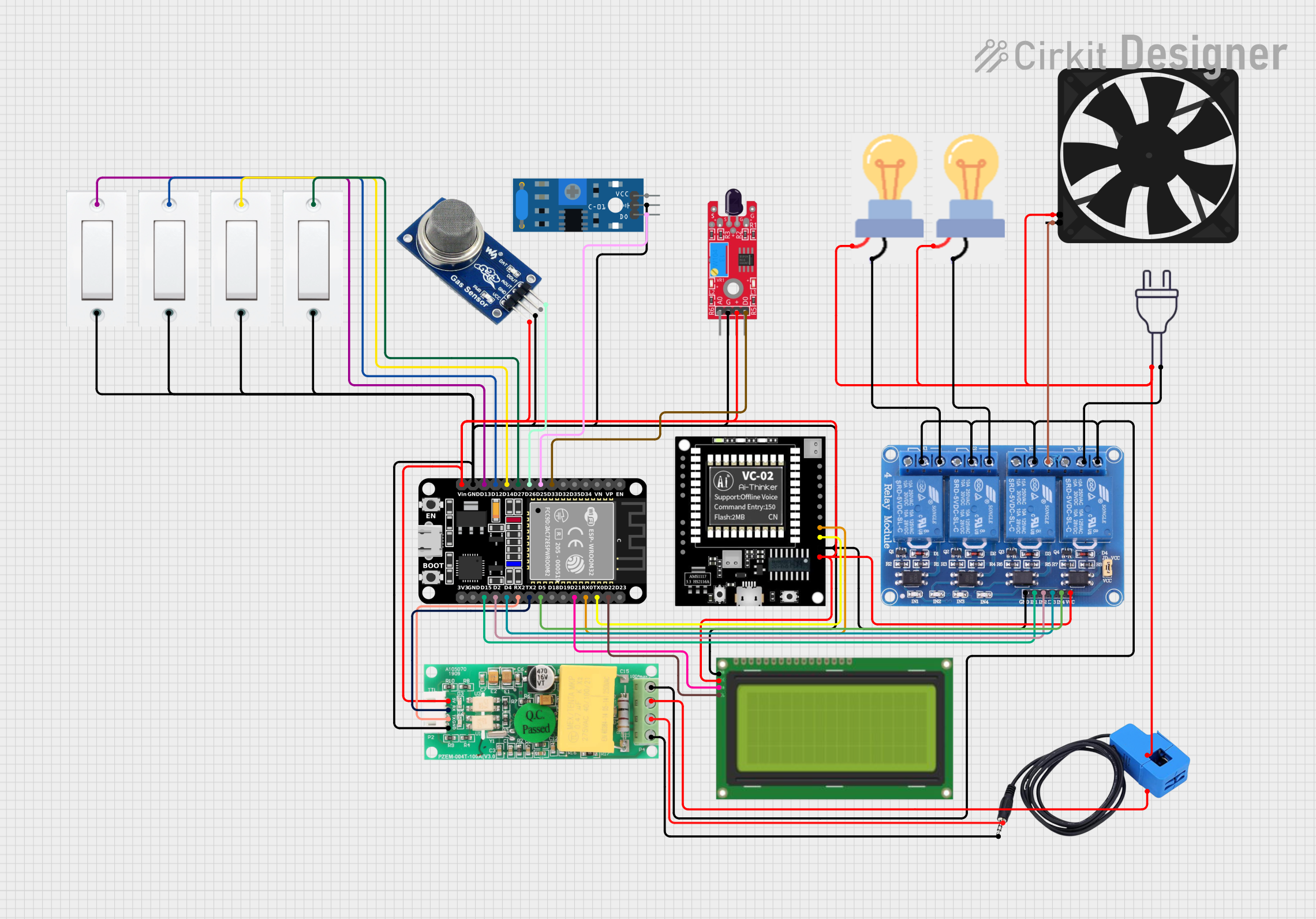
This is a smart environmental monitoring and control system featuring an ESP32 microcontroller interfaced with a PZEM004T for power monitoring, relay modules for actuating bulbs and a fan, and an LCD for user interface. It includes flame, gas, and vibration sensors for safety monitoring purposes.
Open Project in Cirkit DesignerExplore Projects Built with E Stop
ESP32-Based Sensor Monitoring System with OLED Display and E-Stop
This circuit features an ESP32 microcontroller that interfaces with a variety of sensors and output devices. It is powered by a Lipo battery through a buck converter, ensuring a stable voltage supply. The ESP32 collects data from a DHT11 temperature and humidity sensor and a vibration sensor, controls a buzzer, and displays information on an OLED screen. An emergency stop (E Stop) is connected for safety purposes, allowing the system to be quickly deactivated.
Open Project in Cirkit DesignerElectromechanical Pump Control Circuit with Emergency Stop
This circuit is designed to control a pump using a contactor that is manually operated by a switch and can be overridden by an emergency stop. The contactor enables power from an AC power outlet to the pump, and the emergency stop can interrupt the power circuit for safety purposes.
Open Project in Cirkit DesignerESP32-Based Environmental Monitoring System with Emergency Stop and Display
This circuit features an ESP32 microcontroller interfaced with various sensors and output devices. A temperature sensor (LM35) and a hall sensor provide environmental data, while a real-time clock (RTC DS3231) keeps track of time. The circuit includes a buck converter to regulate power from a LiPo battery, an emergency stop (E Stop) for safety, a buzzer for audible alerts, and a seven-segment display (TM1637) for visual feedback. The ESP32 manages sensor readings, time tracking, and user interface components.
Open Project in Cirkit DesignerESP32-Based Smart Environmental Monitoring System with Relay Control
This is a smart environmental monitoring and control system featuring an ESP32 microcontroller interfaced with a PZEM004T for power monitoring, relay modules for actuating bulbs and a fan, and an LCD for user interface. It includes flame, gas, and vibration sensors for safety monitoring purposes.
Open Project in Cirkit DesignerTechnical Specifications
- Type: Normally Closed (NC) or Normally Open (NO) contacts, depending on configuration.
- Voltage Rating: Typically 24V to 240V AC/DC (check specific model for exact rating).
- Current Rating: 1A to 10A (varies by model).
- Actuation Force: Approximately 5-10N (varies by design).
- Mounting: Panel-mounted with a standard 22mm or 30mm diameter hole.
- Reset Mechanism: Twist-to-release or pull-to-release, depending on the model.
- Ingress Protection (IP) Rating: Commonly IP65 or higher for industrial environments.
Pin Configuration and Descriptions
| Pin Label | Description | Type |
|---|---|---|
| NC | Normally Closed contact | Safety circuit |
| NO | Normally Open contact (optional) | Signal circuit |
| COM | Common terminal for NC/NO contacts | Power connection |
Usage Instructions
Wiring the E Stop:
- Connect the NC (Normally Closed) terminal in series with the power supply line of the machine or circuit. This ensures that pressing the E Stop will break the circuit and cut power.
- Optionally, use the NO (Normally Open) terminal for signaling purposes, such as triggering an alarm or notifying a control system.
Mounting:
- Drill a 22mm or 30mm hole in the control panel, depending on the E Stop's size.
- Secure the E Stop switch using the provided mounting hardware, ensuring it is easily accessible in case of an emergency.
Resetting the E Stop:
- After activation, reset the switch by twisting or pulling it, depending on the model. Ensure the circuit is safe to re-energize before resetting.
Important Considerations:
- Always verify the voltage and current ratings of the E Stop to ensure compatibility with your system.
- Regularly inspect the switch for wear or damage, especially in harsh environments.
- Test the E Stop periodically to confirm proper functionality.
Example: Connecting an E Stop to an Arduino UNO
The E Stop can be used with an Arduino UNO to monitor its state and trigger actions when pressed.
Circuit Diagram
- Connect the NC terminal of the E Stop to a digital input pin on the Arduino (e.g., pin 2).
- Use a pull-up resistor (10kΩ) to ensure a stable HIGH signal when the switch is not pressed.
Code Example
// Define the pin connected to the E Stop
const int eStopPin = 2; // Digital pin 2

void setup() {
  pinMode(eStopPin, INPUT_PULLUP); // Configure pin as input with internal pull-up
  Serial.begin(9600); // Initialize serial communication for debugging
}

void loop() {
  // Read the state of the E Stop
  int eStopState = digitalRead(eStopPin);

  if (eStopState == LOW) {
    // E Stop is pressed (NC contact is open)
    Serial.println("Emergency Stop Activated!");
    // Add code here to shut down the system or trigger an alarm
  } else {
    // E Stop is not pressed
    Serial.println("System Running Normally");
  }

  delay(500); // Delay for stability and to reduce serial output frequency
}
Troubleshooting and FAQs
Common Issues
E Stop does not cut power:
- Ensure the NC terminal is correctly wired in series with the power supply line.
- Verify that the switch is not damaged or stuck.
E Stop does not reset:
- Check if the twist-to-release or pull-to-release mechanism is functioning properly.
- Inspect for debris or mechanical obstructions.
Arduino does not detect E Stop activation:
- Confirm the wiring between the E Stop and the Arduino.
- Ensure the pull-up resistor is correctly connected or use the internal pull-up resistor in the Arduino.
FAQs
Can I use the E Stop with high-voltage systems?
- Yes, but ensure the E Stop's voltage and current ratings match the system's requirements.
How often should I test the E Stop?
- It is recommended to test the E Stop at least once a month or as per your organization's safety protocols.
Can I use the E Stop in outdoor environments?
- Yes, provided the E Stop has an appropriate IP rating (e.g., IP65 or higher) for protection against dust and water.
By following this documentation, you can safely and effectively integrate an E Stop switch into your system, ensuring reliable emergency shutdown functionality.