
How to Use VS1838B IR Receiver: Examples, Pinouts, and Specs
 Design with VS1838B IR Receiver in Cirkit Designer
Introduction
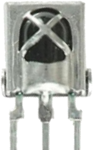
The VS1838B is an infrared (IR) receiver module designed to detect and decode infrared signals, typically from remote controls. It operates at a frequency of 38 kHz, which is the standard modulation frequency for most IR remote controls. The module is compact, highly sensitive, and features a built-in demodulator, making it ideal for use in consumer electronics, home automation systems, and hobbyist projects.
Explore Projects Built with VS1838B IR Receiver
 Open Project in Cirkit Designer
 Open Project in Cirkit Designer
 Open Project in Cirkit Designer
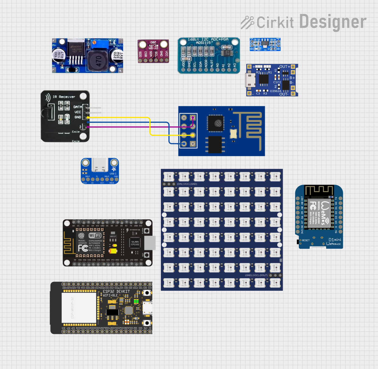 Open Project in Cirkit Designer
Explore Projects Built with VS1838B IR Receiver
Open Project in Cirkit DesignerOpen Project in Cirkit DesignerOpen Project in Cirkit DesignerOpen Project in Cirkit DesignerCommon Applications
- Remote control signal reception for TVs, DVD players, and other consumer electronics
- Home automation systems
- Arduino and microcontroller-based projects
- IR communication between devices
- Robotics and IoT applications
Technical Specifications
Below are the key technical details of the VS1838B IR receiver module:
| Parameter | Value |
|---|---|
| Operating Voltage | 2.7V to 5.5V |
| Operating Current | 0.4 mA (typical) |
| Carrier Frequency | 38 kHz |
| Reception Distance | Up to 18 meters (depending on IR source) |
| Reception Angle | ±45° |
| Output Signal | Active low |
| Response Time | 400 µs (typical) |
| Dimensions | 7.6 mm × 5.8 mm × 4.2 mm |
Pin Configuration
The VS1838B has three pins, as described in the table below:
| Pin | Name | Description |
|---|---|---|
| 1 | OUT | Output pin for the demodulated IR signal (active low) |
| 2 | GND | Ground pin |
| 3 | VCC | Power supply pin (2.7V to 5.5V) |
Note: Pin numbering may vary depending on the module's manufacturer. Always refer to the datasheet or module markings for accurate pin identification.
Usage Instructions
Connecting the VS1838B to a Circuit
- Power Supply: Connect the VCC pin to a 3.3V or 5V power source, depending on your system's voltage.
- Ground: Connect the GND pin to the ground of your circuit.
- Signal Output: Connect the OUT pin to a digital input pin of your microcontroller or Arduino.
Important Considerations
- Decoupling Capacitor: Place a 10 µF capacitor between VCC and GND to stabilize the power supply and reduce noise.
- Avoid Direct Sunlight: The module's performance may degrade in direct sunlight or under strong ambient IR sources.
- IR LED Alignment: Ensure the IR transmitter (remote control) is aligned within the module's ±45° reception angle for optimal performance.
Example: Using the VS1838B with Arduino UNO
Below is an example of how to use the VS1838B with an Arduino UNO to decode IR signals from a remote control.
Circuit Diagram
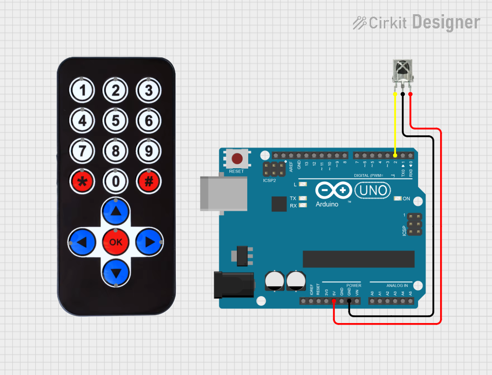
- Connect the VS1838B's VCC pin to the Arduino's 5V pin.
- Connect the GND pin to the Arduino's GND.
- Connect the OUT pin to Arduino digital pin 11.
Arduino Code
#include <IRremote.h> // Include the IRremote library

const int RECV_PIN = 11; // Define the pin connected to the VS1838B OUT pin
IRrecv irrecv(RECV_PIN); // Create an IR receiver object
decode_results results;  // Variable to store decoded IR data

void setup() {
  Serial.begin(9600); // Initialize serial communication
  irrecv.enableIRIn(); // Start the IR receiver
  Serial.println("IR Receiver is ready to decode signals.");
}

void loop() {
  if (irrecv.decode(&results)) { // Check if a signal is received
    Serial.print("IR Code: ");
    Serial.println(results.value, HEX); // Print the received code in HEX format
    irrecv.resume(); // Prepare to receive the next signal
  }
}
Note: Install the
IRremotelibrary in the Arduino IDE before uploading the code. You can do this via the Library Manager.
Troubleshooting and FAQs
Common Issues
No Signal Detected
- Cause: Incorrect wiring or loose connections.
- Solution: Double-check the connections, ensuring VCC, GND, and OUT are properly connected.
Unstable or Noisy Output
- Cause: Power supply noise or interference from ambient IR sources.
- Solution: Add a decoupling capacitor (10 µF) between VCC and GND. Avoid using the module in direct sunlight or near strong IR sources.
Short Reception Range
- Cause: Weak IR transmitter or misalignment.
- Solution: Ensure the IR transmitter is within the module's ±45° reception angle and within the specified range (up to 18 meters).
Library Errors in Arduino IDE
- Cause: Missing or outdated
IRremotelibrary. - Solution: Install or update the
IRremotelibrary via the Arduino Library Manager.
- Cause: Missing or outdated
FAQs
Q1: Can the VS1838B work with 3.3V systems?
Yes, the VS1838B operates within a voltage range of 2.7V to 5.5V, making it compatible with both 3.3V and 5V systems.
Q2: What is the maximum distance for signal reception?
The module can receive signals from up to 18 meters, depending on the strength of the IR transmitter and environmental conditions.
Q3: Can I use the VS1838B to transmit IR signals?
No, the VS1838B is an IR receiver module and cannot transmit signals. Use an IR LED for transmission.
Q4: How do I decode signals from different remote controls?
The IRremote library supports decoding signals from most standard remote controls. Use the example code above to capture and analyze the IR codes.
By following this documentation, you can effectively integrate the VS1838B IR receiver into your projects and troubleshoot common issues with ease.